What is Nutanix AHV Metro Availability?
Nutanix AHV Metro Availability is a feature that allows two Nutanix clusters, typically in different physical locations, to work together as if they were a single system.
More...
It continuously mirrors data between both sites in real time, so if one site goes down due to a power outage, fat finger, natural disaster, disgruntled employee running a lastday.bat - the other site can automatically take over with no data loss and only a minimal short downtime. This ensures high availability and business continuity, allowing operations to continue seamlessly even during major outages.

Architecture Design
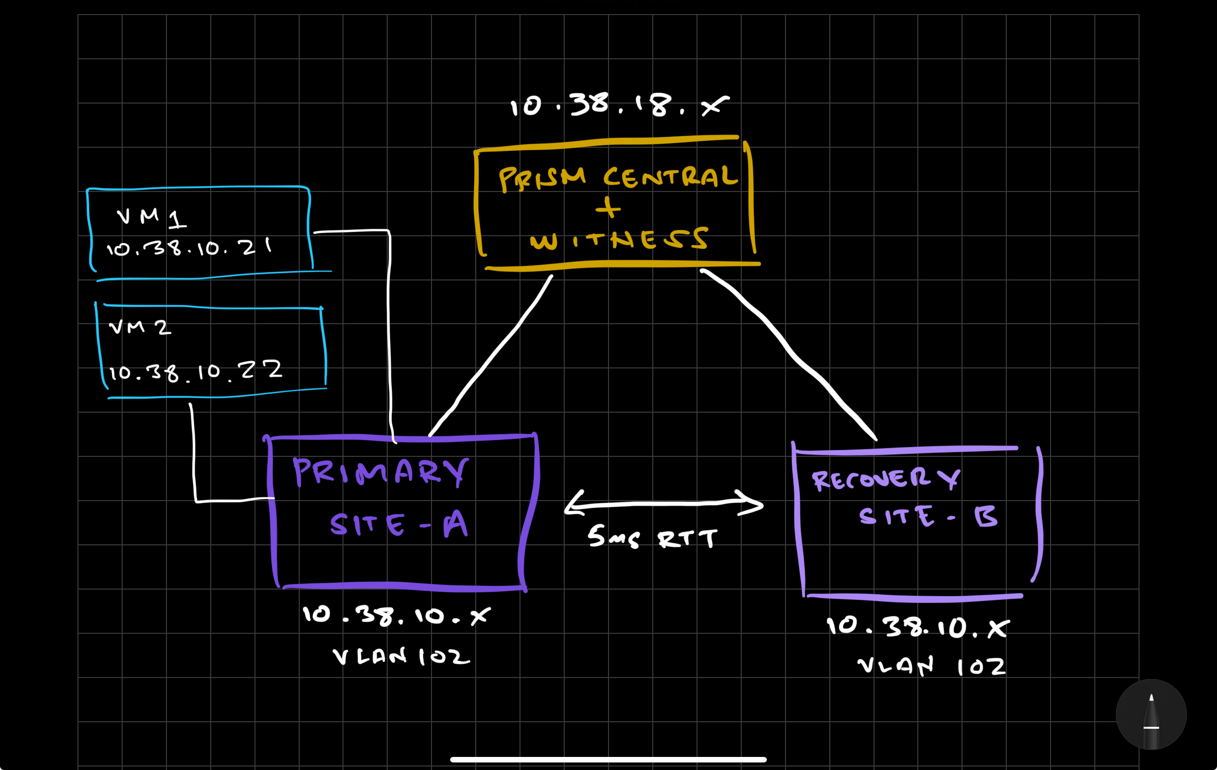
This AHV Metro Availability setup will consist of the following 3 sites:
Primary-Site-A | PC-Witness | Recovery-Site-B |
|---|
This would be a typical scenario most companies would have implemented if they were thinking about any synchronous replication between two sites.
Prerequisites
There are a few Requirements and Recommendations that we need to do prior to setting up AHV Metro Availability. This guide was created using the following versions in this configuration.
AOS | AHV | Prism Central |
|---|---|---|
1. Licensing
We'll need to make sure we have the correct licensing in order to take advantage of AHV Metro which requires the Ultimate version of our NCI licensing.
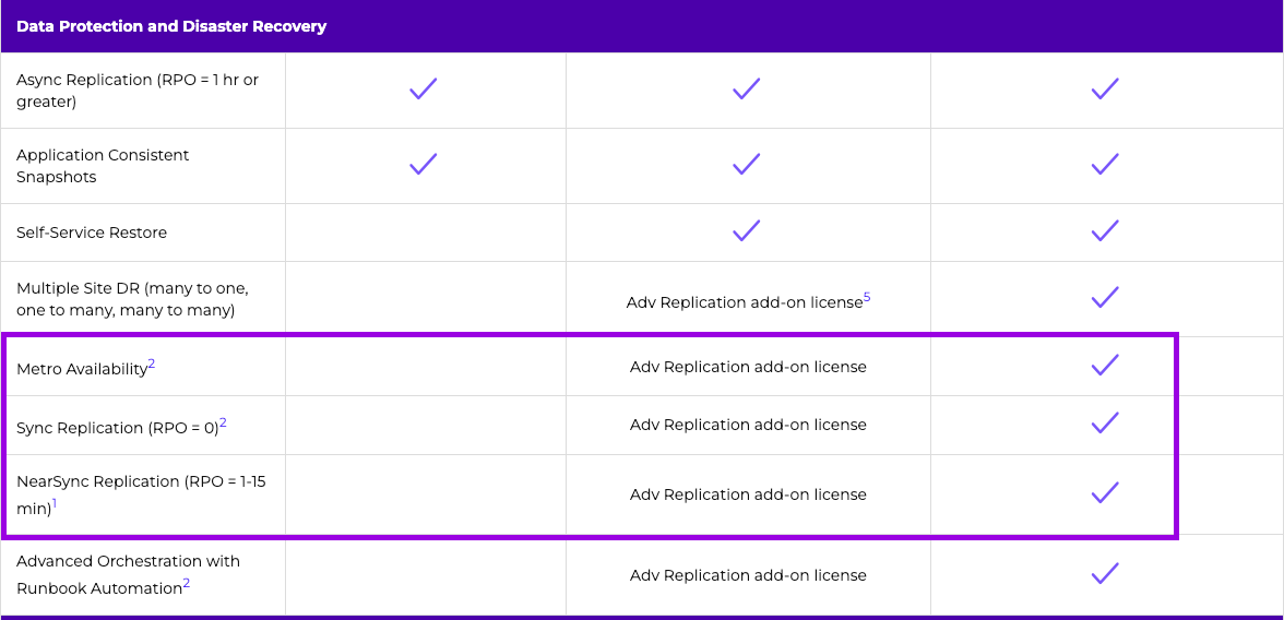
2. Sites/Clusters + Register Prism Central
First, make sure you identify your defined primary and recovery site. Then make sure those clusters are registered with your Prism Central which will sit on a third site based on the design above.
**Note: Skip to the next step if you already have clusters connected to a Prism Central.
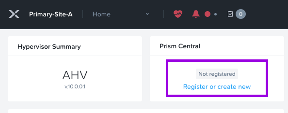
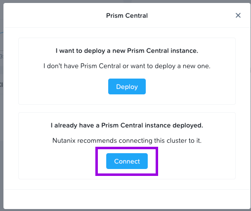
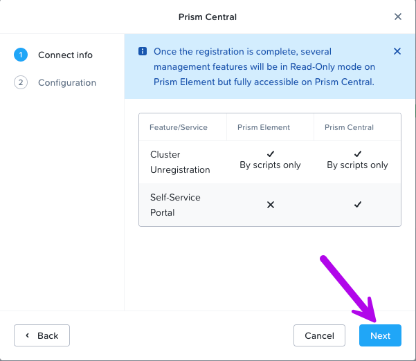
1. Login to your Prism Element cluster and click on Register under the Prism Central widget. Another small window will pop-up. Choose the option that best suits your scenario. For this config I'll click on Connect since I already have a Prism Central deployed.
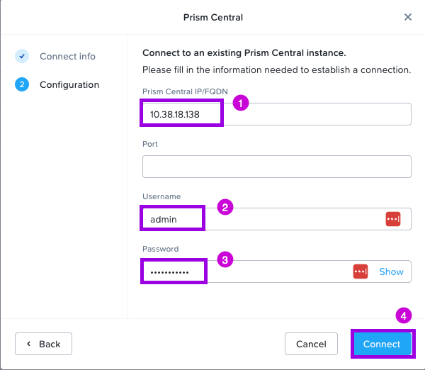
2. Click Next in this window. Under Configuration, fill in the following fields. Prism Central IP, Username & Password. Once done, click on Connect.
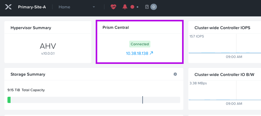
You should now see that your cluster is connected to Prism Central.

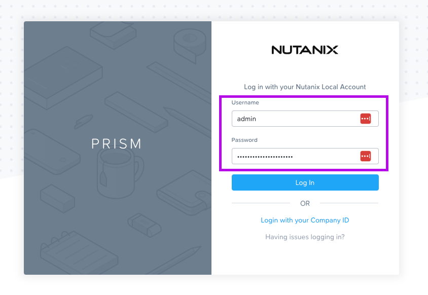
3. Login to Prism Central to validate the clusters were registered successfully.
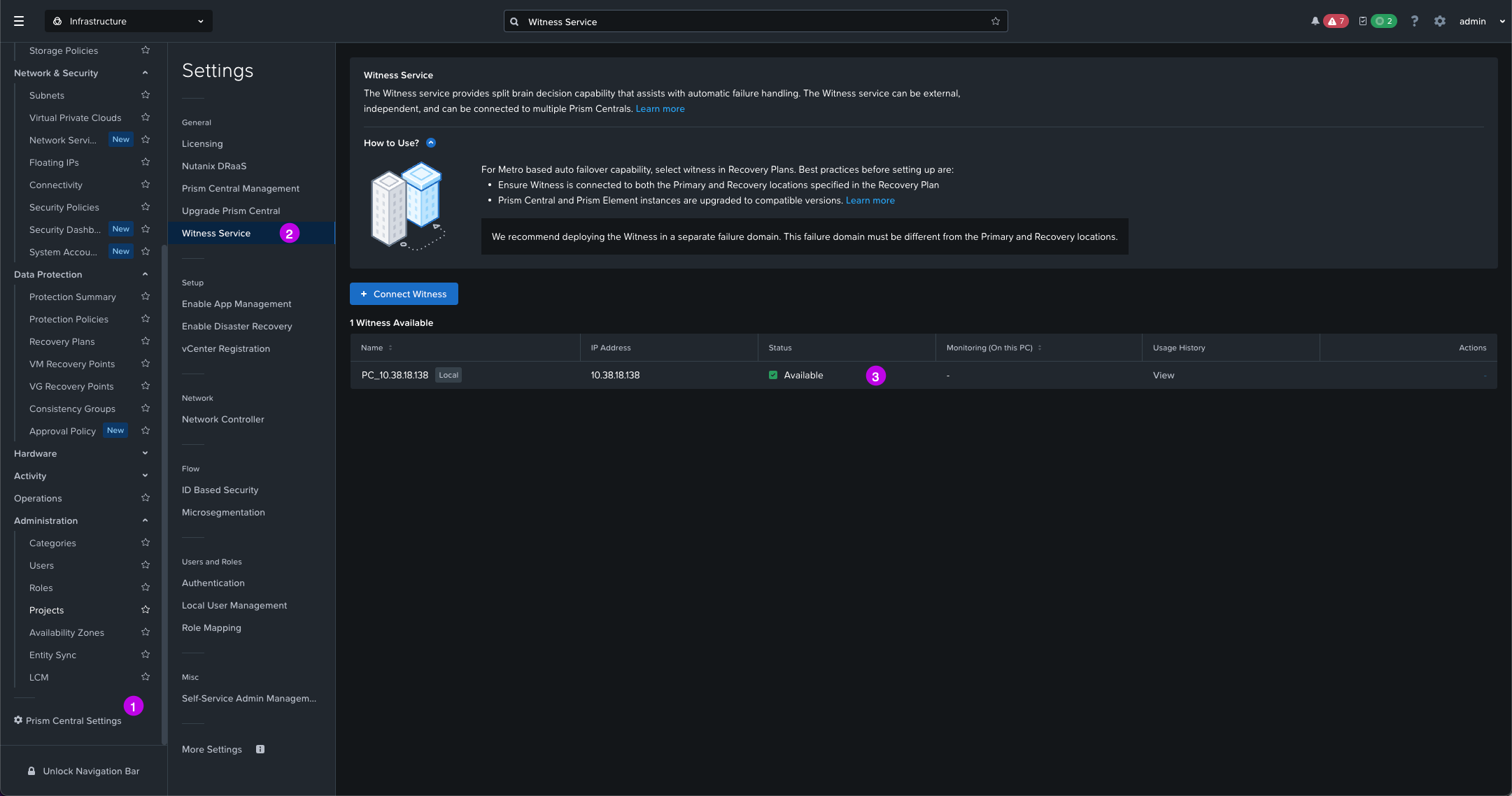
4. While you are in Prism Central navigate on the left menu over to Prism Central Settings > Witness Service. We just want to ensure the Witness Service is showing an Available status.
3. Create Identical Storage Containers
You'll need to create an identically named Storage Container on both the primary and recovery sites.
1. If you aren't already, login to Prism Central.
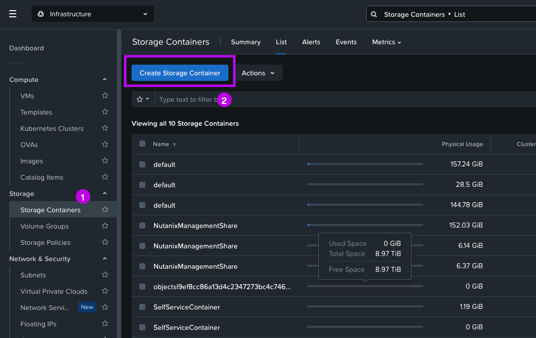
2. Once logged in navigate on the left menu to Storage > Storage Containers then click on Create Storage Container
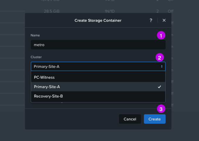
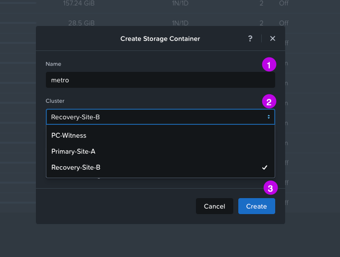
3. In the pop-up window fill in the Name of the storage container (in this demo we'll use the name "metro") and then choose the Cluster where this storage container will exist. We are going to ignore the Advanced Settings option for this demo configuration. Once done click on Create.
4. Then repeat the above process once again to create a storage container on the recovery site. Remember to keep the identical name of the storage container you've just created. This is also case-sensitive!
5. Finally simply validate that you see both newly created Storage Containers on both Primary and Recovery clusters.
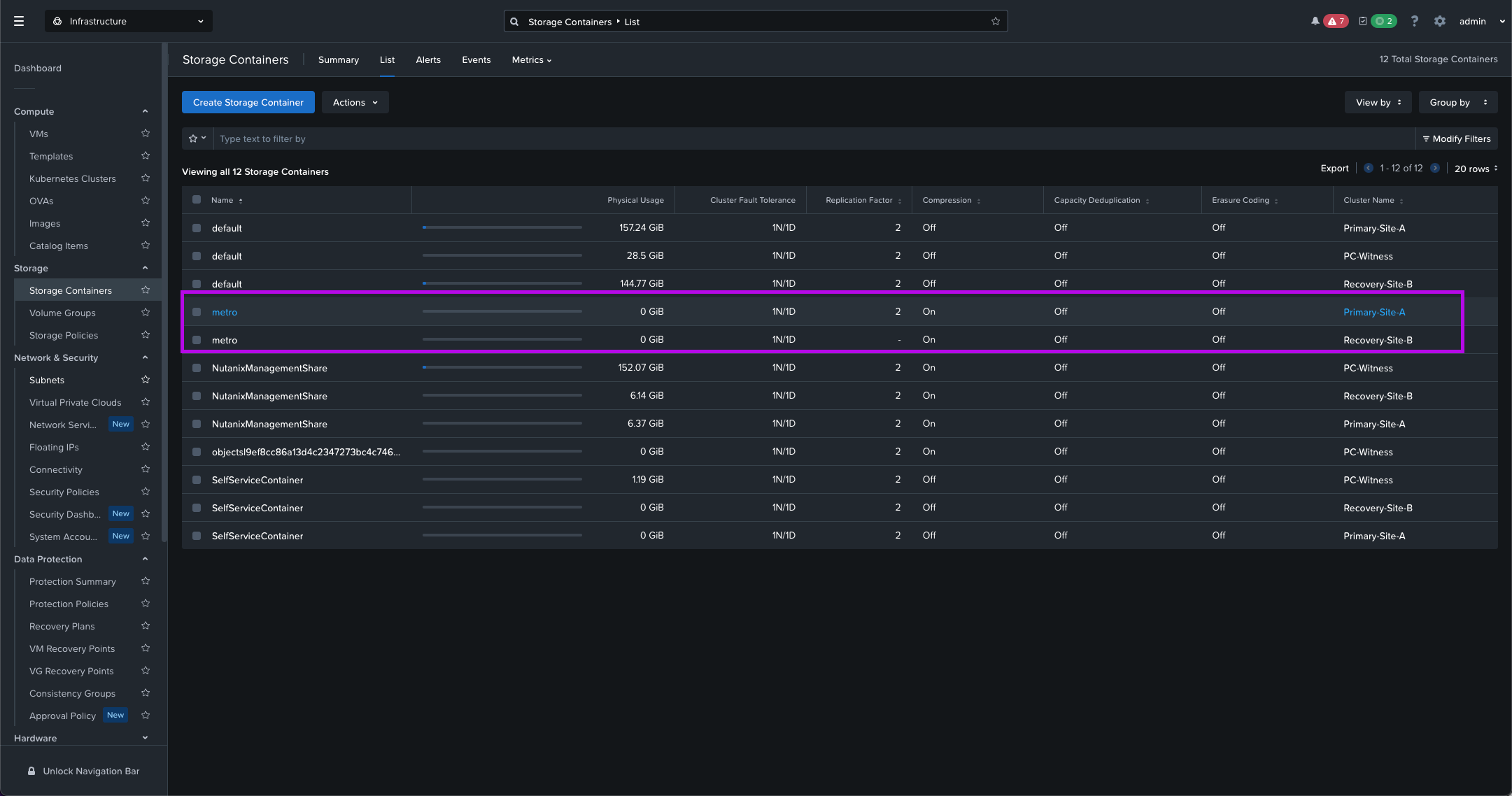
Remember these clusters must have identical names since the underlying replication mechanisms rely on metadata matching.

Wait! Why do we have to create a separate Storage Container again? Can't I use the existing default one?
4. Configure CVM Firewall Ports
Next we'll need to open some firewall ports on both the Primary and Recovery clusters to ensure communication between both clusters. You'll need to first grab the CVM IPs in order to run these commands against. Which we'll do next.
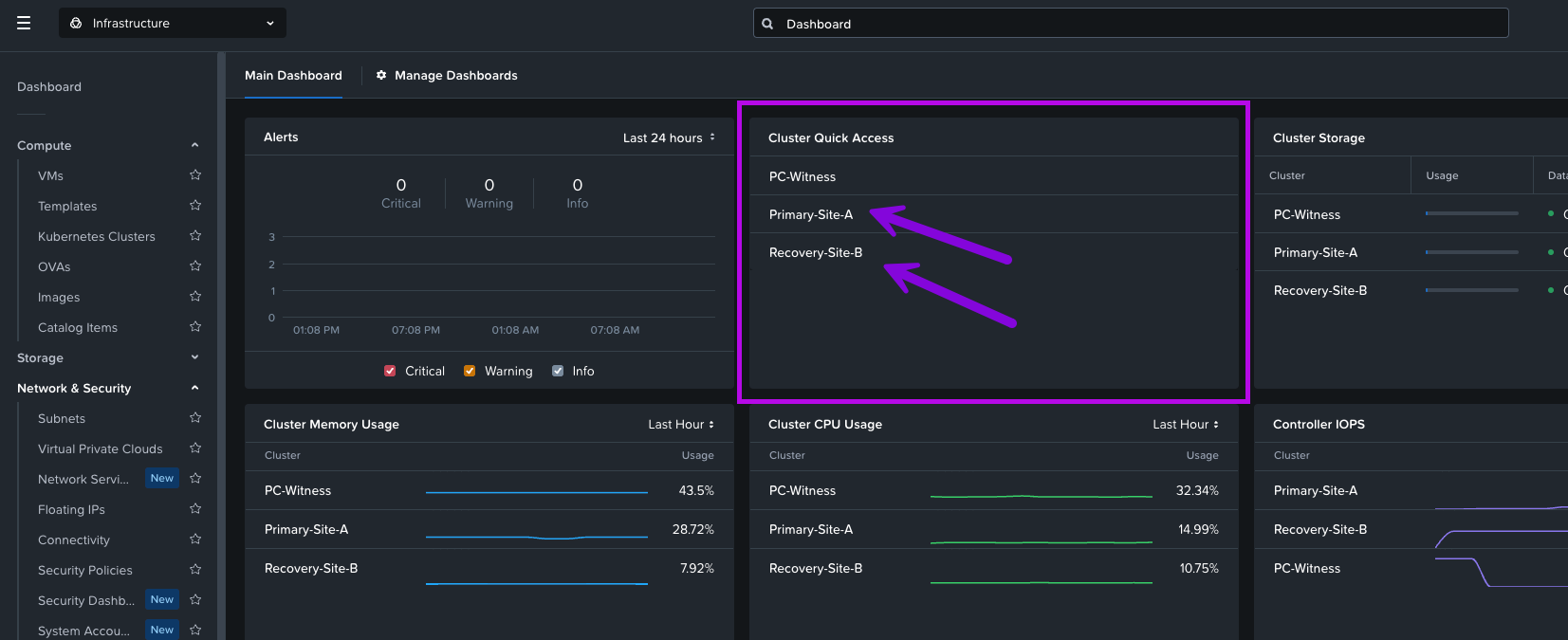
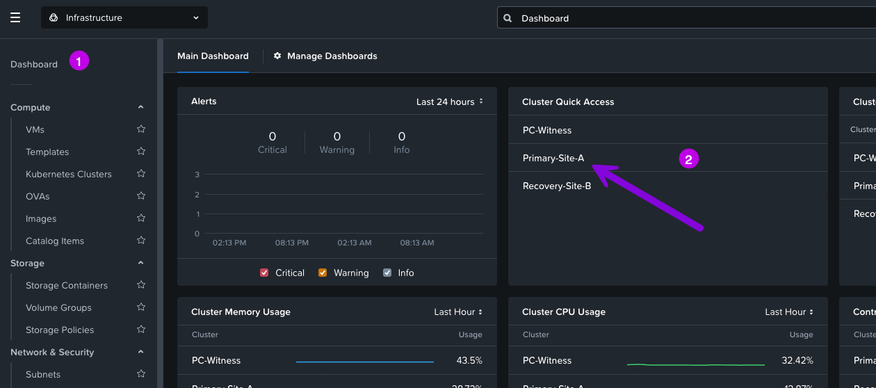
1. From Prism Central navigate to your Dashboard then click on your Primary Cluster from the Cluster Quick Access widget.
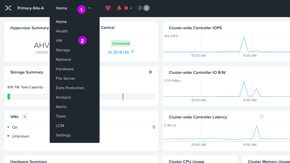
2. A new tab should open and automatically log you into Prism Element for the cluster. From here click on the drop-down and navigate to Home > VM
3. Once you are at the VM view, you may need to change the tab from Overview to Table. From here click on the box next to Include Controller VMs. This will expose the CVM and show you its IP address. In my example, my Primary clusters CVM IP is: 10.38.10.6. Jot this down as we'll need it later. 🙂

4. Next we'll need to grab the cluster Virtual IP or VIP. You can find that by first clicking on the cluster name. A small window will pop-up and display the VIP in the Virtual IP field. My VIP in this example is: 10.38.10.7 (your IP will differ) add this IP to your notes.

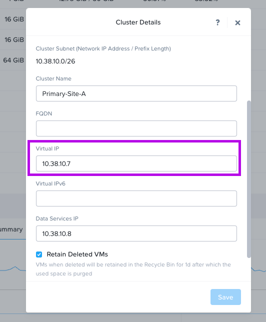
5. Next, do the same exercise for the Recovery cluster and jot down the IP for both the CVM and VIP.

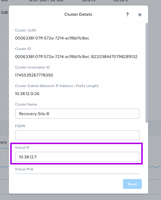
6. Once you have the CVM IPs from both the Primary and Recovery clusters we'll need to run some commands against each CVM by logging into a CVM in Primary and a CVM in Recovery.
**Note: This example environment only has single-node clusters. You may have multiple nodes in a cluster with multiple CVM's managing each node.**
This is the command we'll be running:
allssh 'modify_firewall -f -r <comma separated list of Cluster CVM IPs>,<Cluster VIP> -p 2030,2036,2073,2090 -i eth0'
It's best to open up a text editor and edit the commands we'll be running. Something similar to this.
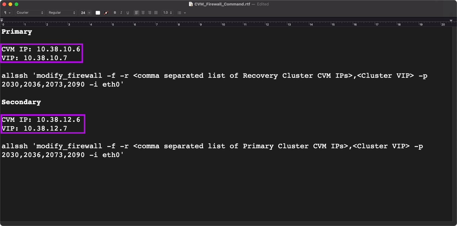
Let's edit the command with the CVM and VIP IPs we obtained. We'll need to add the CVM and VIP IP from our Recovery environment to the command line for our Primary and vise versa.
For example: After logging into the Primary CVM (10.38.10.6) I'll need to run this command:
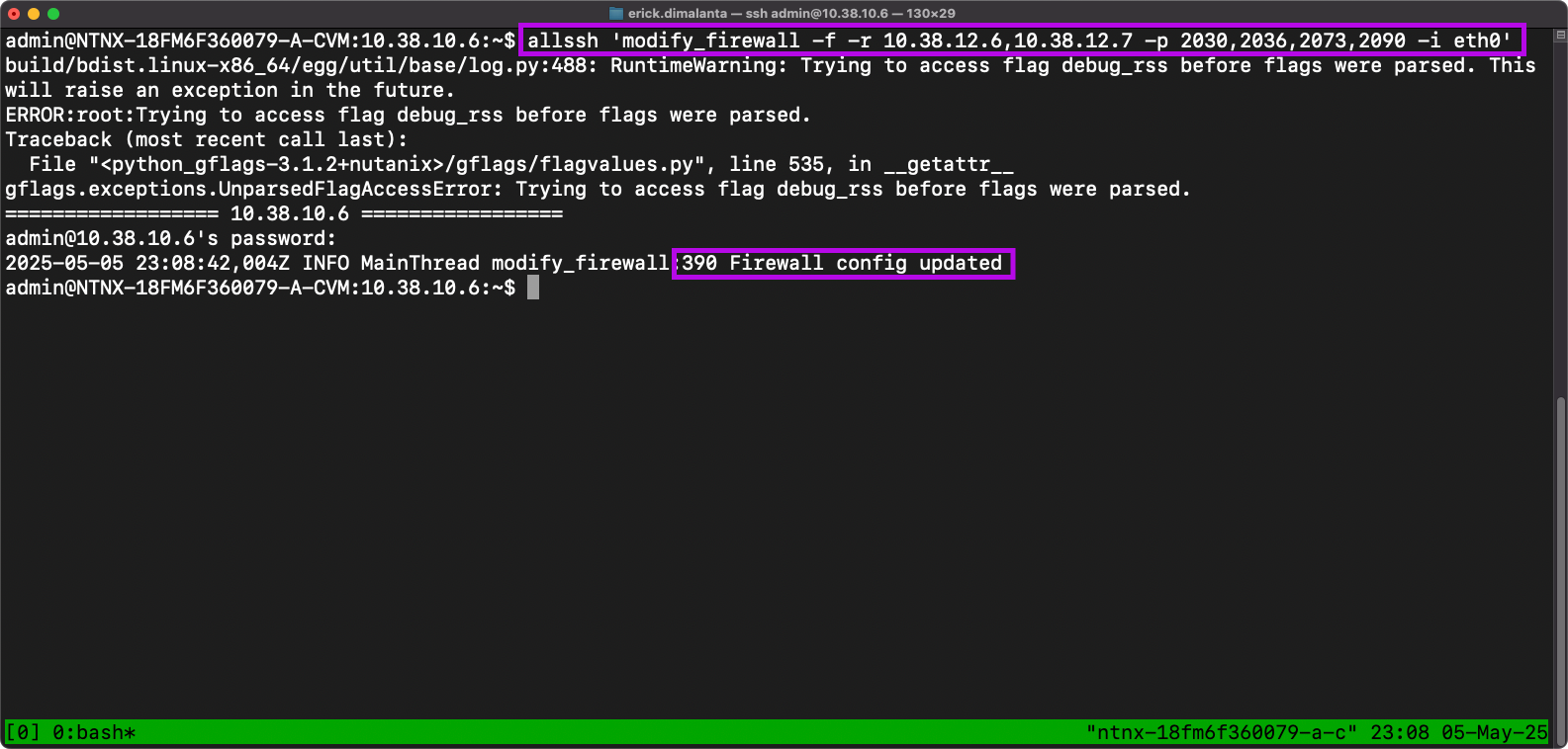
allssh 'modify_firewall -f -r 10.38.12.6,10.38.12.7 -p 2030,2036,2073,2090 -i eth0'
Now simply edit the commands from your text editor to place the IPs in the correct location. Similar to this.
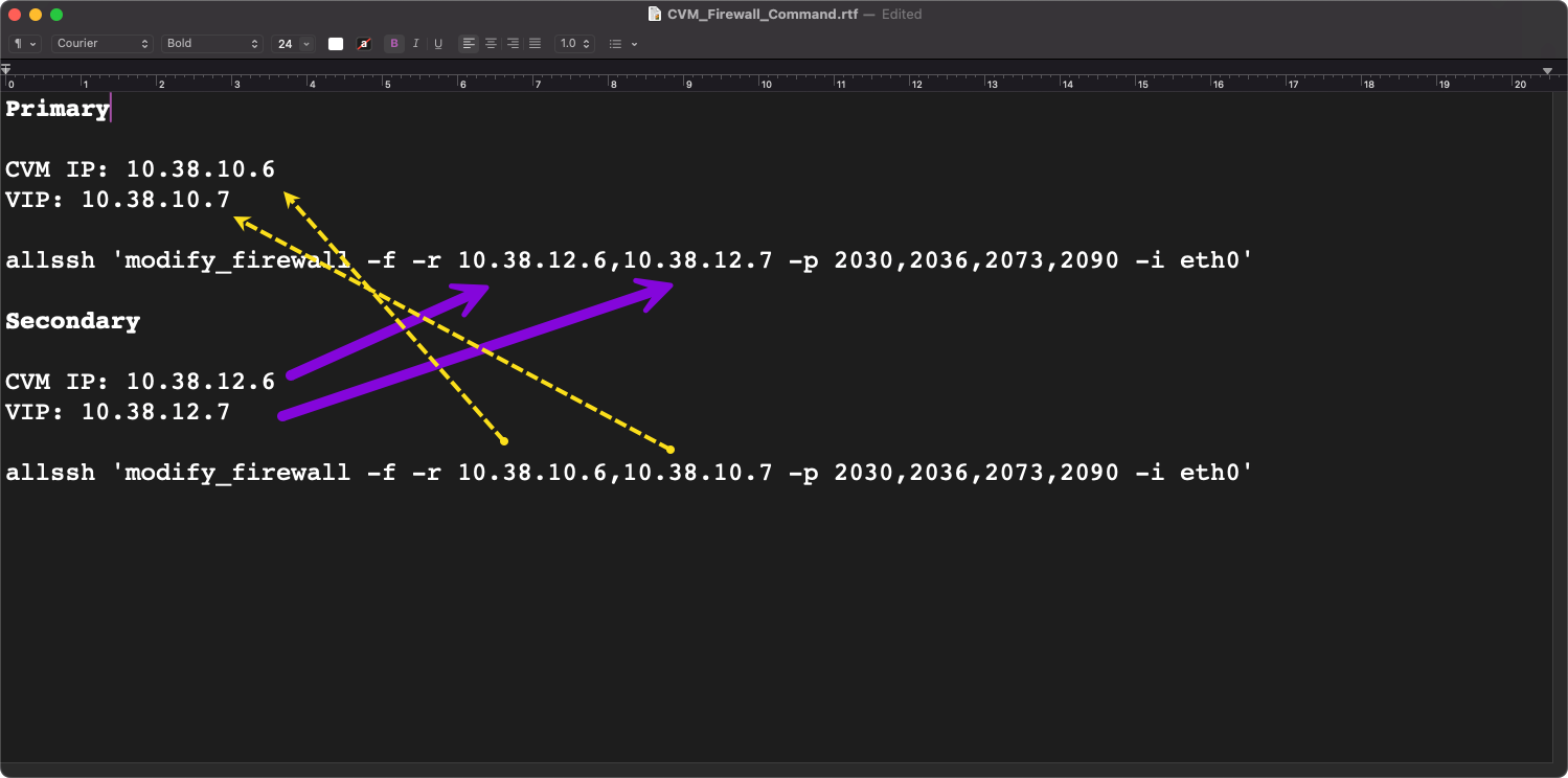
This will allow these IPs to have communication over the ports that are defined in both the Primary and Recovery sites.
7. Now that we have our commands ready, we can login to each respective CVM and run them.
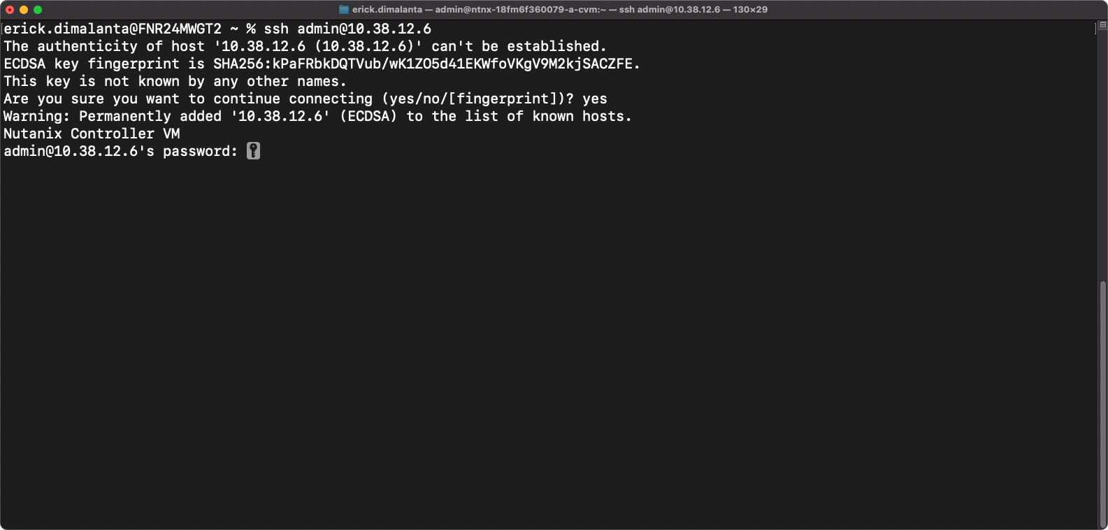
- SSH into your Primary CVM
- Type yes when prompted
- Enter CVM password
- Once your session has logged in, run the Primary command in your text editor that has the Recovery cluster CVM & VIP IPs.
- Enter CVM password when prompted
- Firewall config updated is the desired message
Repeat the steps on your Recovery CVM.
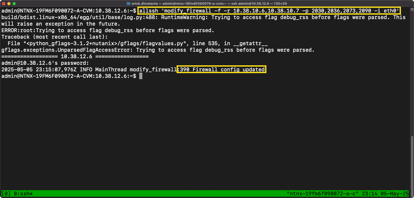
- SSH into your Recovery CVM
- Type yes when prompted
- Enter CVM password
- Once your session has logged in, run the Secondary command in your text editor that has the Primary cluster CVM & VIP IPs.
- Enter CVM password when prompted.
- Firewall config updated is the desired message

Ok cool! So, can you make sense of what the specific port numbers are responsible for?
5. Ensure VM Networks Exist On Both Clusters
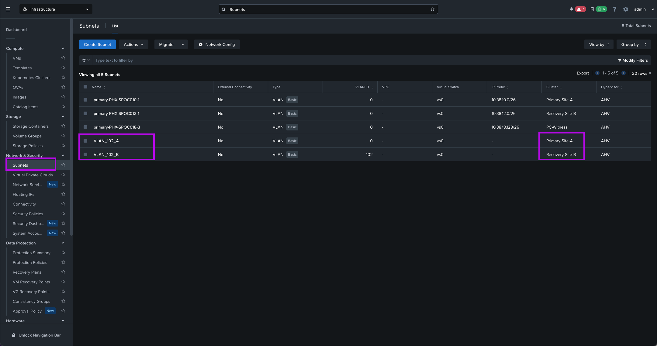
When a site failure occurs, you don't want to be the individual that didn't configure the networks on both ends to make sure the VMs that power on in the Recovery cluster have network connectivity.
Just make sure you create the Subnets for the VLANs you want to add on both sides. Make sure with your networking team that the VLAN IDs exist in both environments and those VLANs are tagged on the physical switches which are then trunked down to our virtual switch.
Do this unless you have a pure L2 stretch network which is on the same broadcast domain.
With this, most of the pre-work is complete and now we can move on to the AHV Metro Availability config. 😎

AHV Metro Availability Setup
So now that we've completed all of the prerequisites we can move forward with the Metro Availability setup. One of the first things we'll need to do is make sure the VMs that we are targeting to protect are using that "metro" Storage Container we created above.
1. Migrate VM Disk To New Storage Container
Identify which VMs you are targeting to participate in AHV MA. Follow the steps below to update the VM disk.
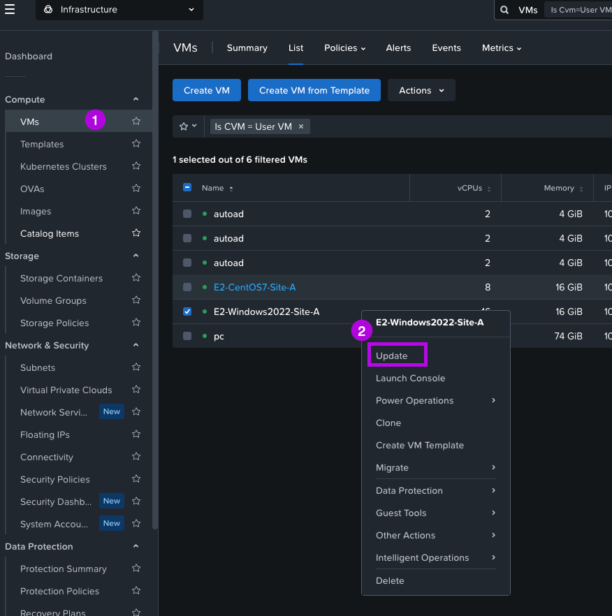
1. Right click on the VM and select Update
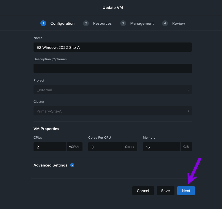
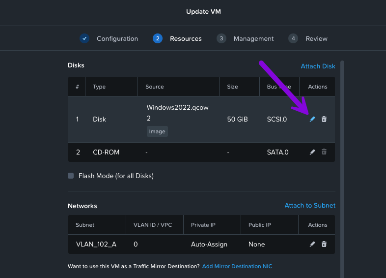
2. An Update VM window will pop-up. From here click on Next. On the next screen you'll want to click on the pencil icon next to the disk we'll need to move.
3. From here an Update Disk window will pop up, navigate down to the Storage Container field and click on the drop down menu to select "metro" then afterwards click on Save.
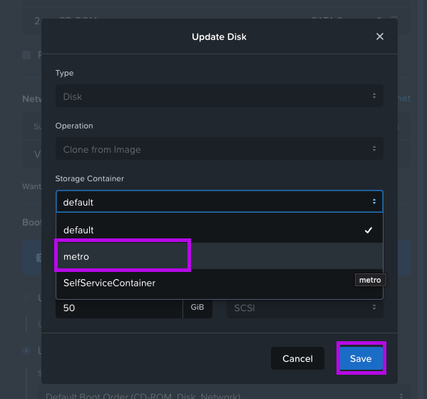
4. Once you've done that, you'll be back in the Update VM page. Simply click on Save in the bottom part of the window to finish up.
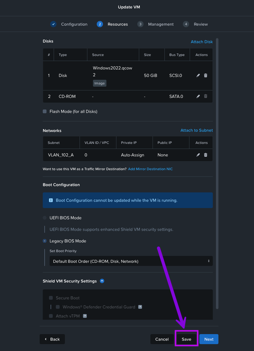
5. Monitor the recent tasks to see the disk migration status. Go grab a drink and come back in a few minutes.

Once complete, do this for any other subsequent VMs that will be participating in Metro Availability.
2. Create Categories
We'll have to create a category in order to group our VMs that will be protected with synchronous replication. In order to do so, follow these steps.
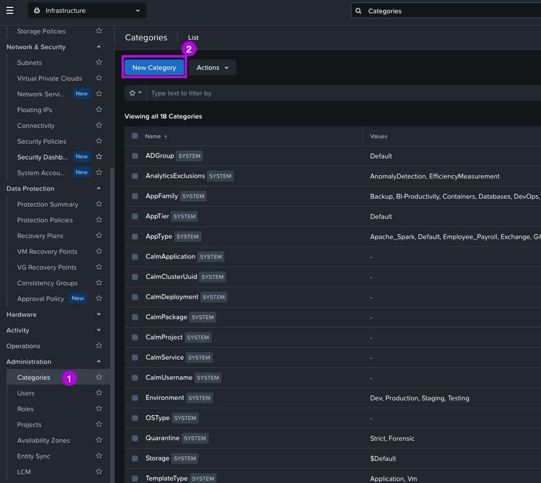
1. Use the left menu to scroll down to the Administration > Categories menu. From here click on New Category.
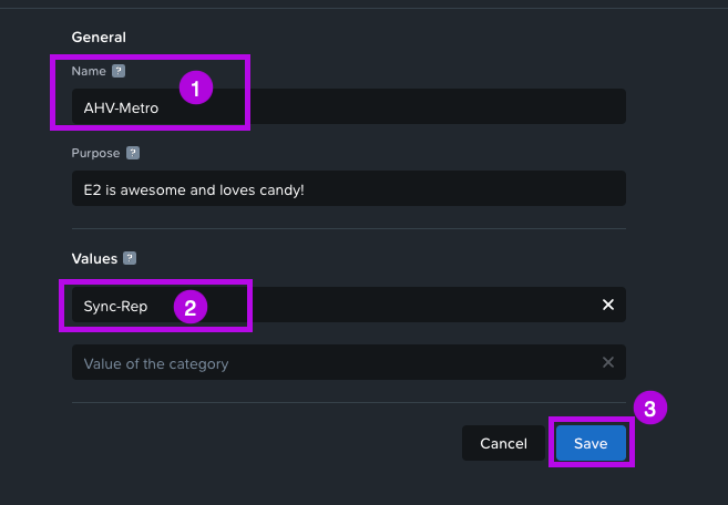
2. On the next screen set a name under General and next set a Value. For this demo, I'll set the following:
Name: AHV-Metro
Value: Sync-Rep
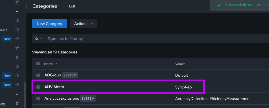
When done, simply click on Save. You should now see your category in the Categories list.
2a. Add VMs to Category
After creating our category, we'll need to assign all the VMs that we are targeting to protect within this newly created category.
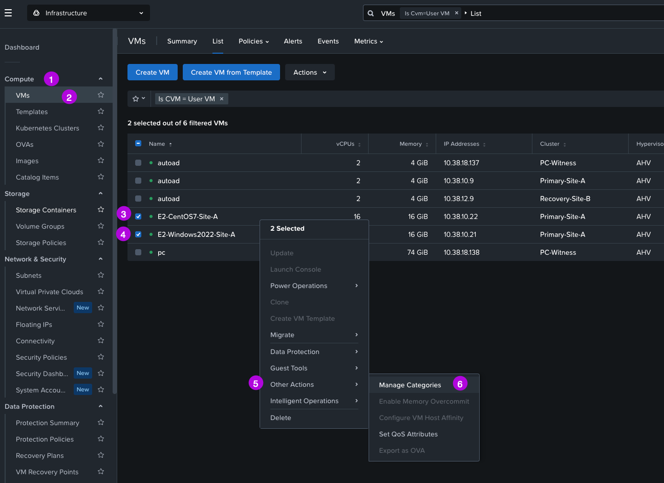
1. Navigate to Compute > VMs then select the VMs that will need to be added to this category. Once selected right click and navigate within the menu to Other Actions > Manage Categories
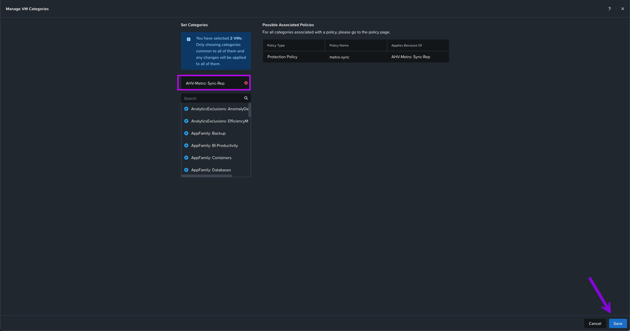
2. In the Manage VM Categories window click in the search field to search for the category we've just created. In this instance I'm looking for AHV-Metro: Sync-Rep. Click on the Blue + to the left of the category name. Once added, click on Save in the bottom right.
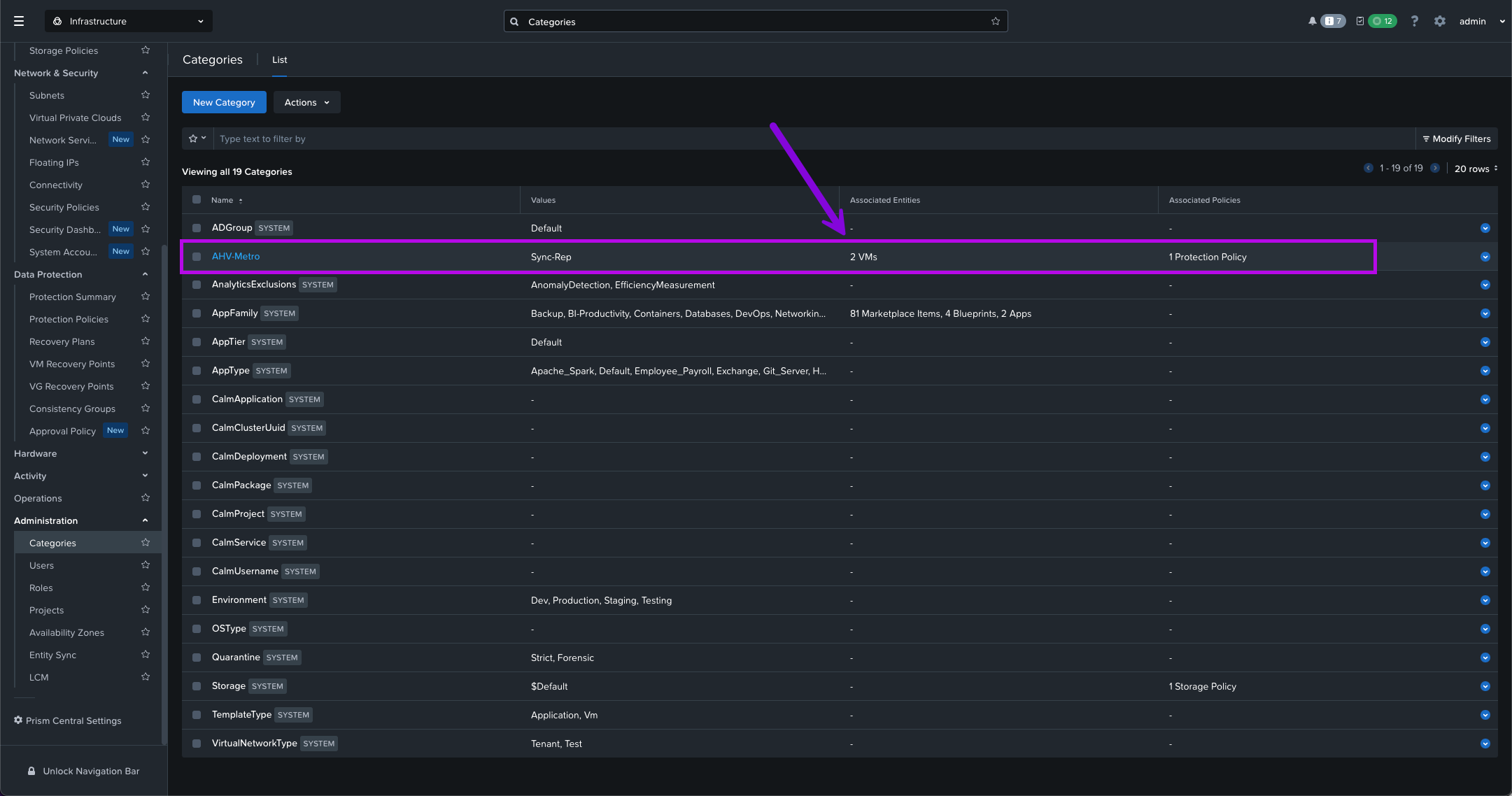
We will then use this category to protect all the VMs within it. If you navigate down to Administration > Categories you'll be able to see the category and associated number of VMs. Clicking into this will drill down on which VMs are added to this category.
3. Create Protection Policy
Now we'll create our Protection Policy which will help to automate the creation and replication of recovery points for our VMs. Follow the steps below:
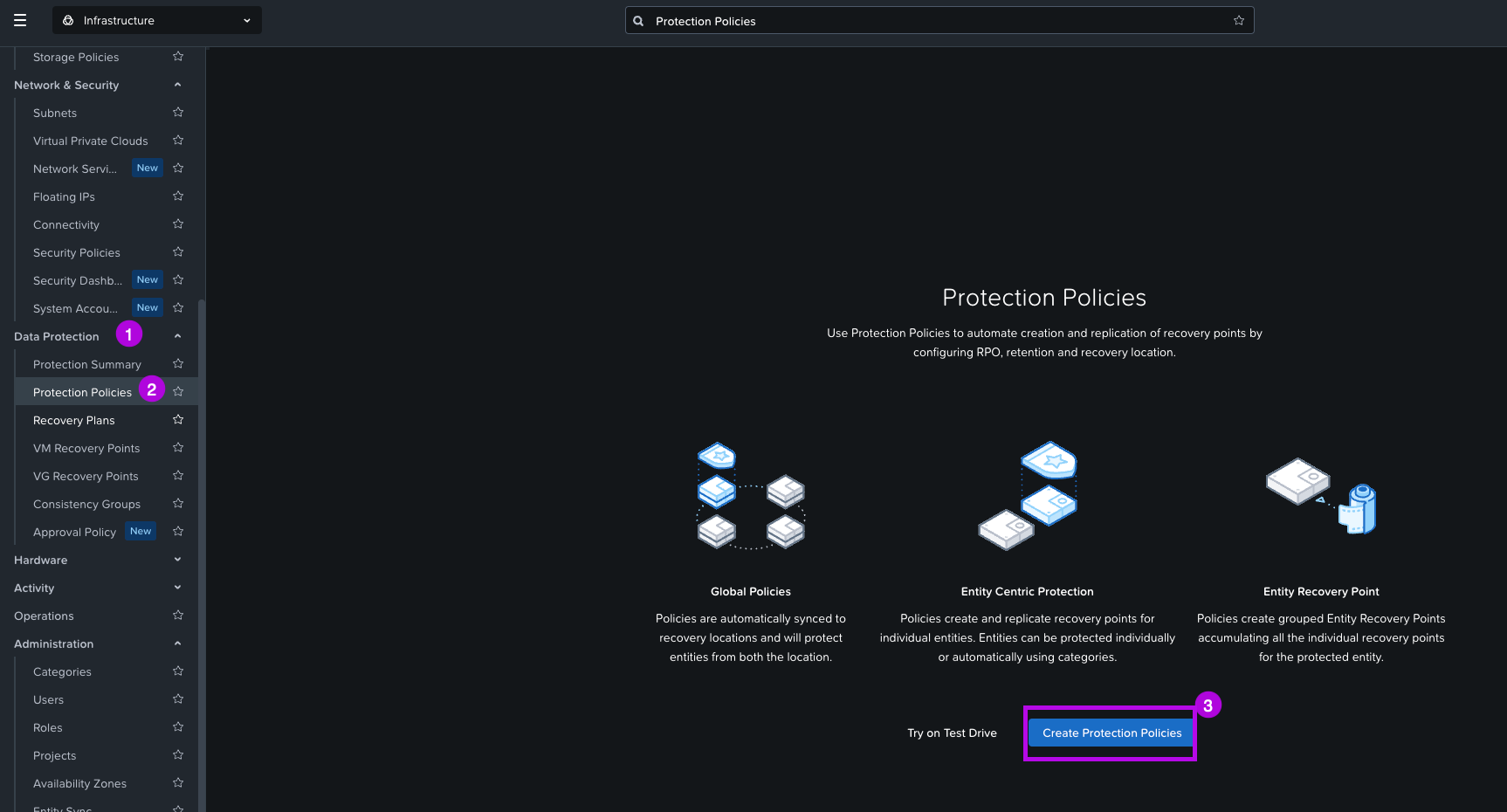
1. Navigate on the left side of the menu to Data Protection > Protection Policies. From here click on Create Protection Policies.
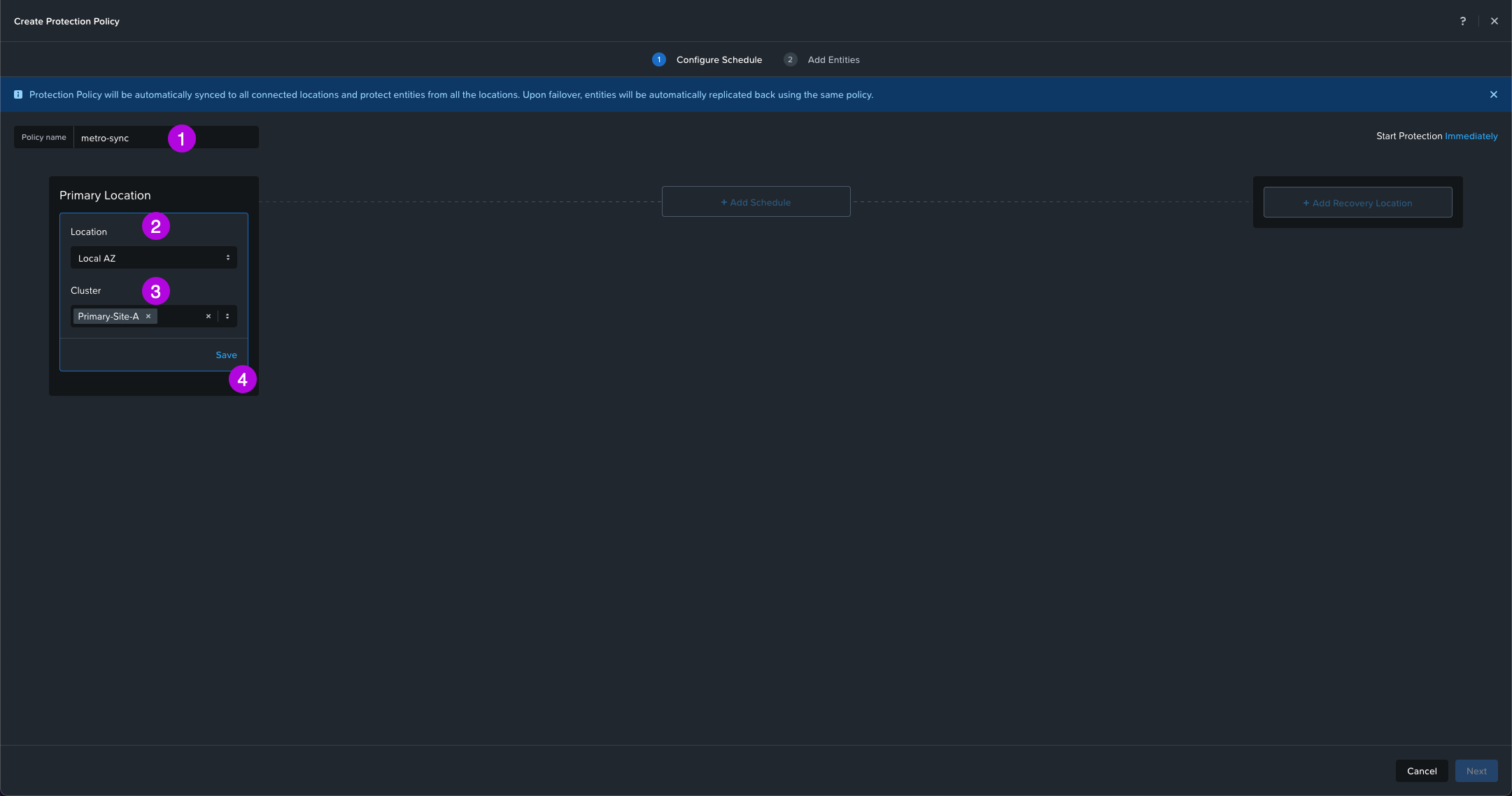
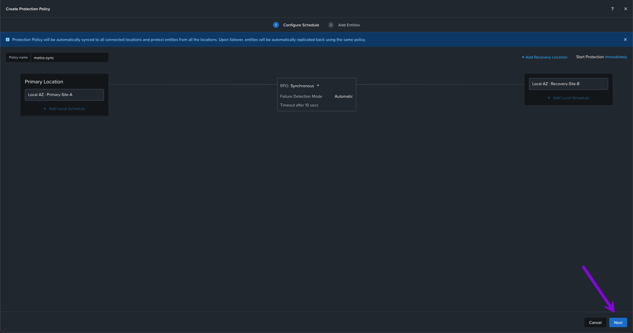
2. On this next screen enter in the Policy name. In this example we'll use the name "metro-sync" then select your Location AZ on whichever Availability Zone your primary cluster is in. Next, click on the drop down and choose which Cluster for your Primary Location. I'll choose Primary-Site-A which is the cluster I defined in the architecture design. Finally click on Save.
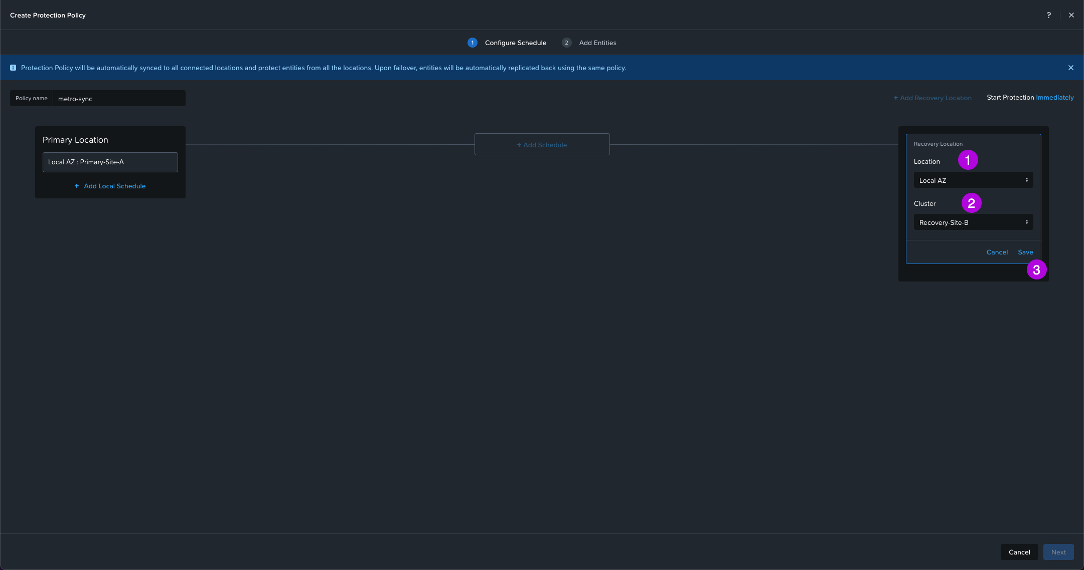
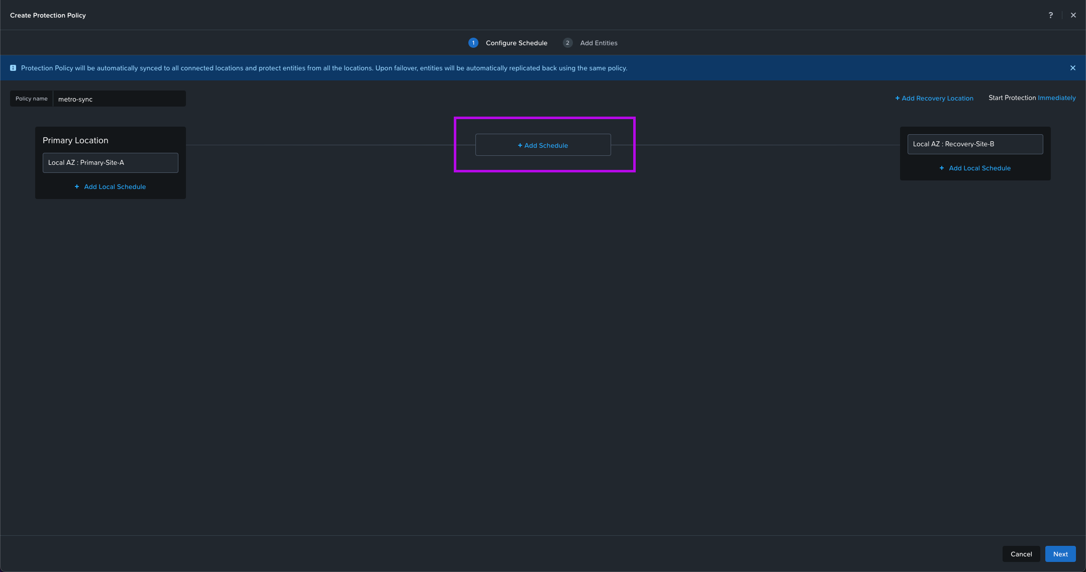
3. We'll do the same for the Recovery Location. Select your AZ Location, Cluster then click on Save. My cluster will be Recovery-Site-B. From here the middle option + Add Schedule will light up. Click on it to continue.
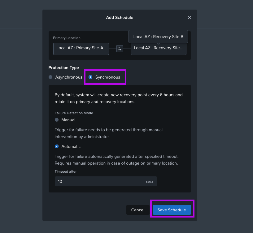
4. A new Add Schedule window will pop up. From here select Synchronous. Leave the selected Failure Detection Mode to the default which is Automatic with a 10 sec timeout. Then click on Save Schedule. Once this window closes, click on Next in the bottom right.
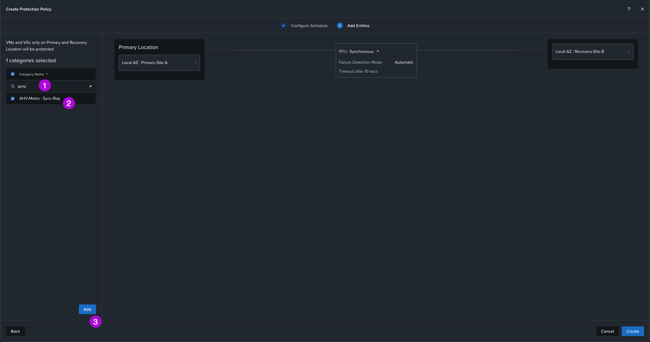
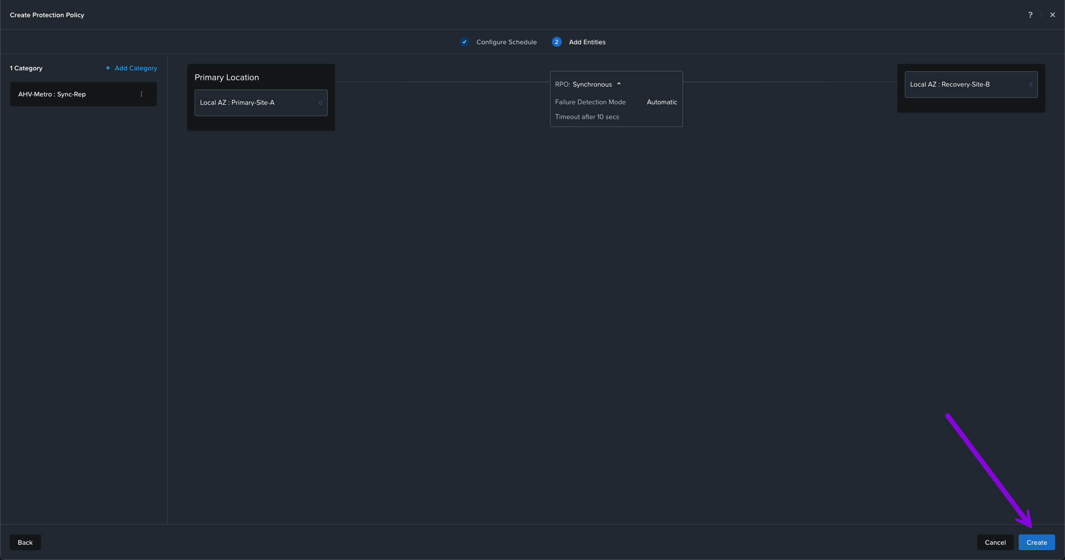
5. Here we'll need to search for the Category we created in the Create Categories step. Our category we defined was called AHV-Metro: Sync-Rep. Once selected, click on Add. Then afterwards, click on Create in the bottom right.
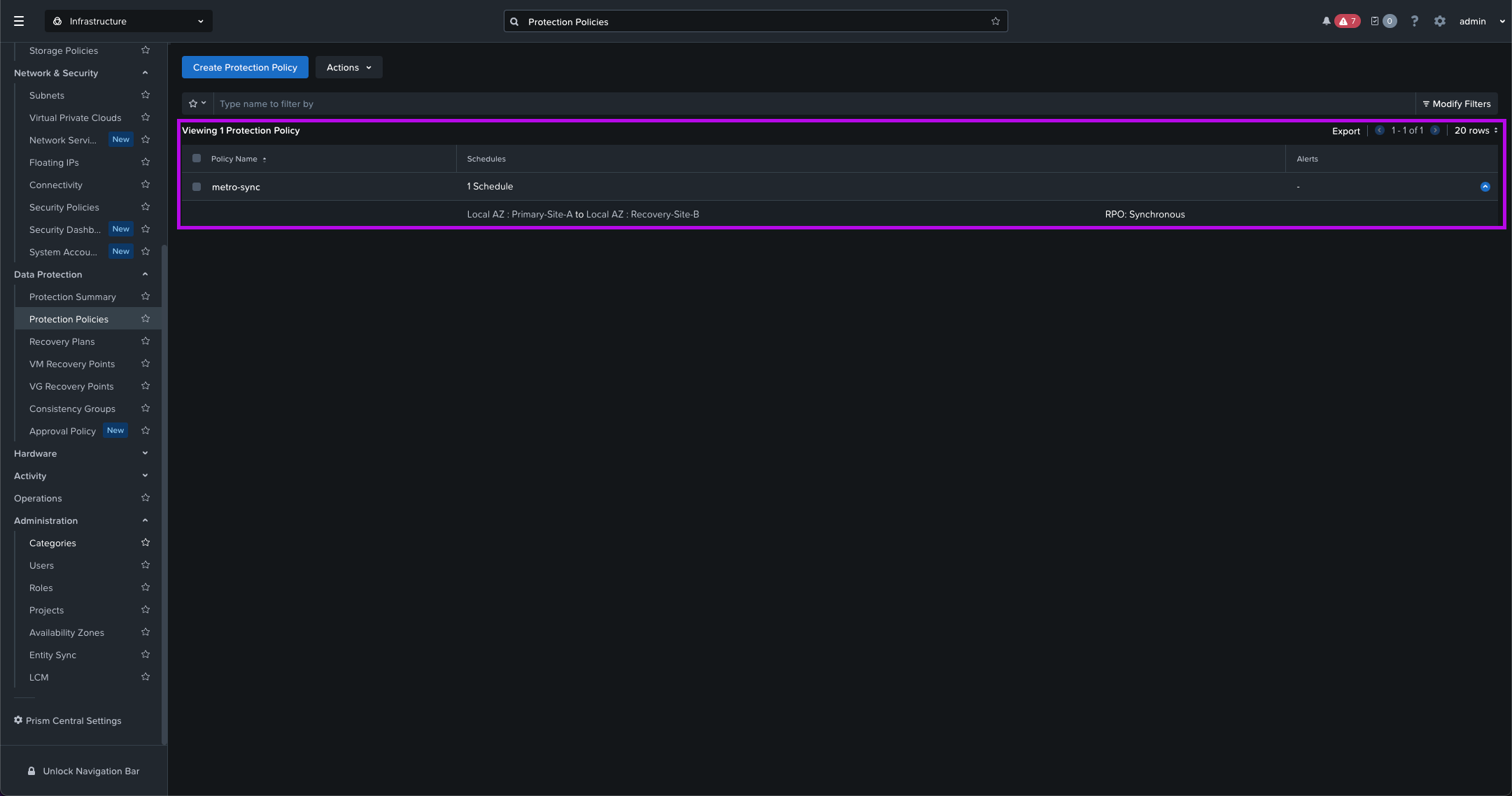
You should now have a newly created Protection Policy displayed.
4. Create Recovery Plan
Now that we have our Protection Policy setup, next we'll need to define a Recovery Plan. Let's configure with the steps below.
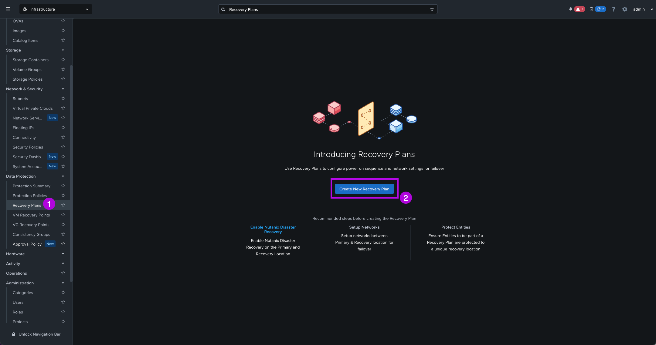
1. Navigate on the left side menu down to Data Protection > Recovery Plans. From here click on Create New Recovery Plan
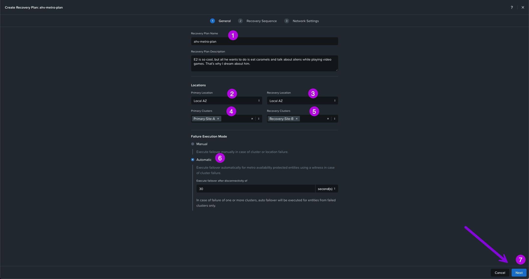
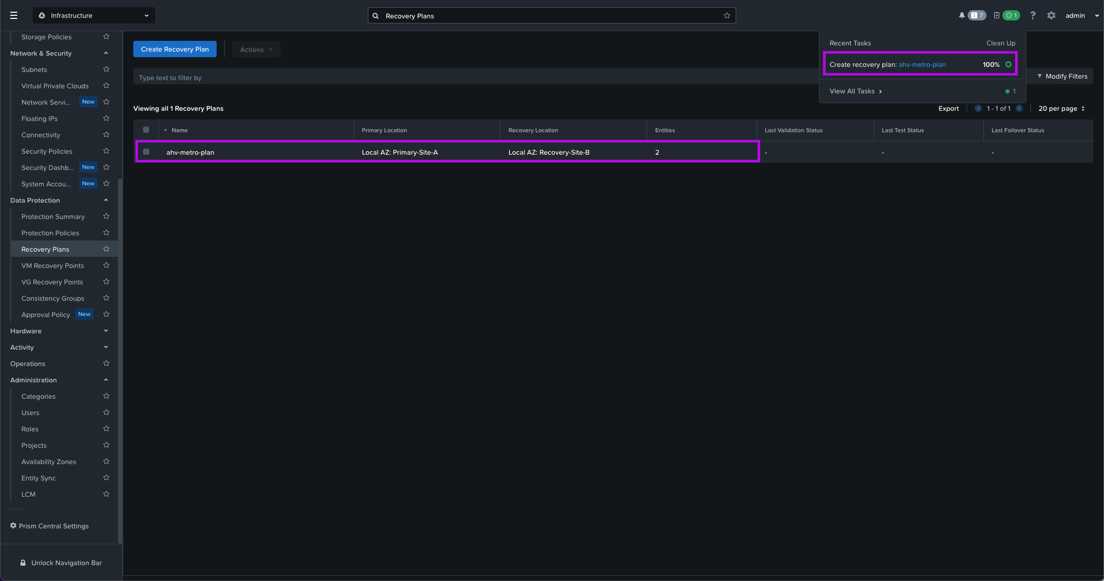
2. Next enter in your Recovery Plan Name. For this setup my name will be ahv-metro-plan, then choose your Primary and Recovery AZ locations. Next select your Primary and Recovery Clusters. For the Failure Execution Mode choose Automatic which will allow the Witness to acknowledge an outage has occurred and automatically start the recovery of workloads on the Recovery site. Once selected keep the default 30 seconds then click on Next to continue on.
**NOTE: For the Recovery Plan Name - Only Alphanumeric, dot, dash, or underscore characters only allowed.**
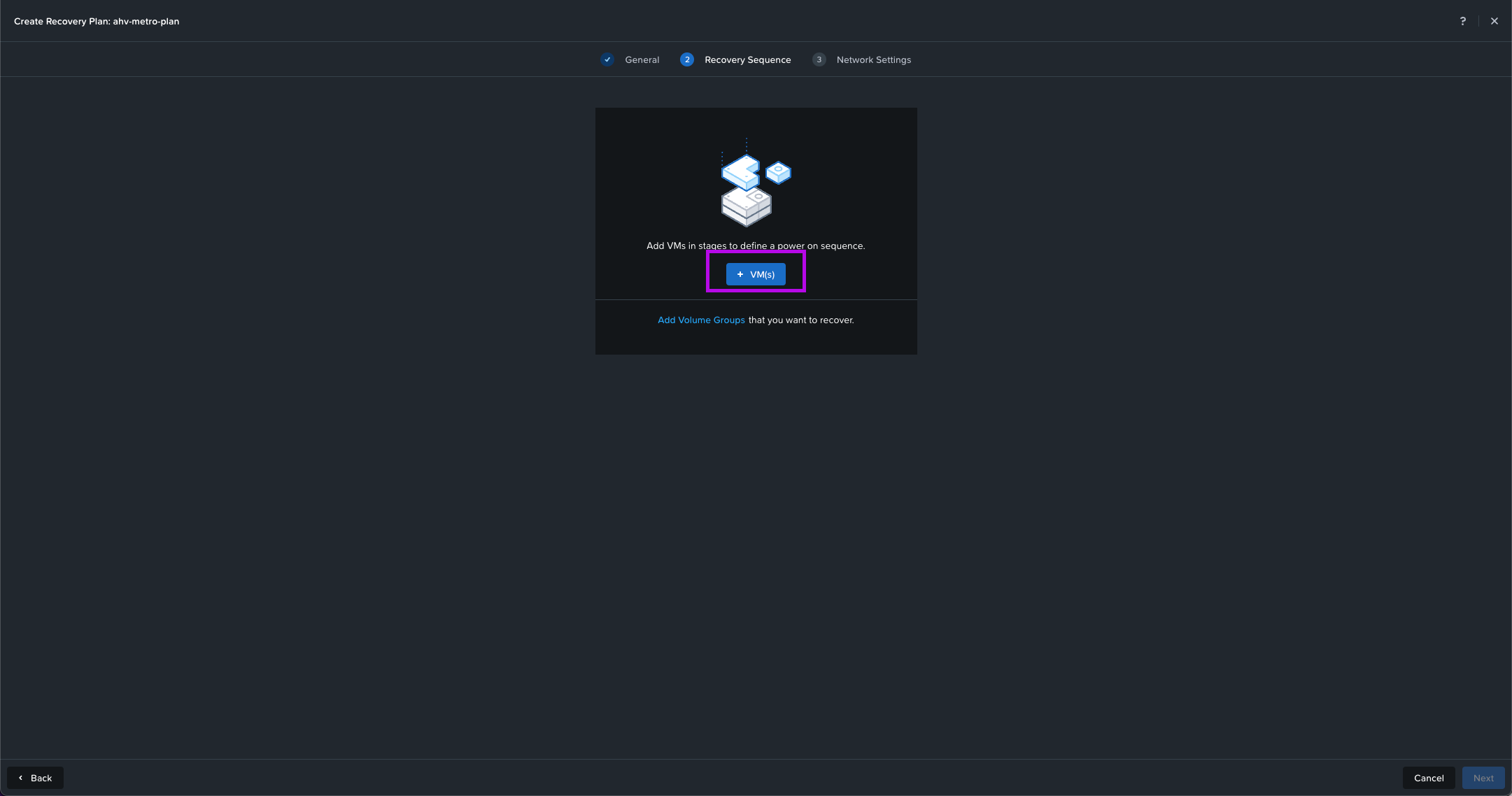
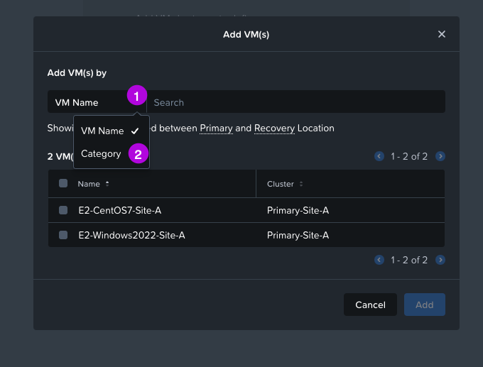
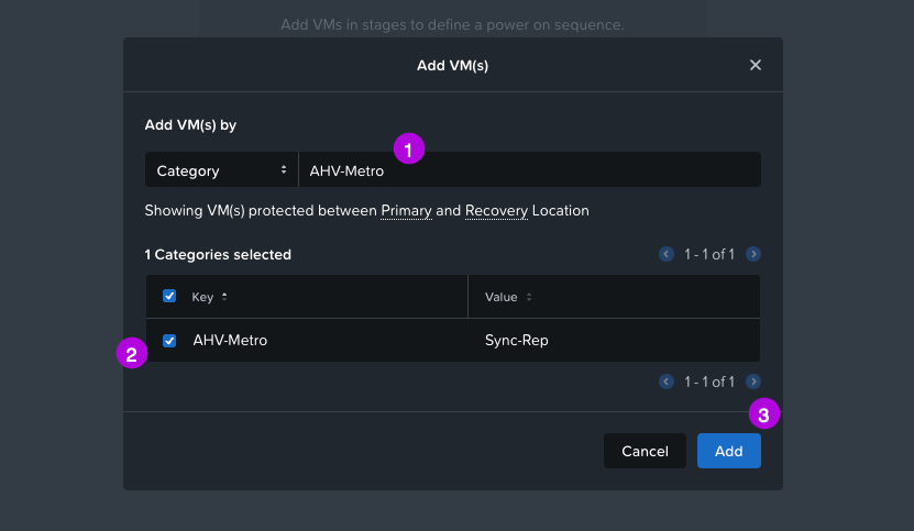
3. On the next screen click for the Recovery Sequence on the + VM(s) button. Click on the drop down under the first option to change VM Name to Category. Search for the category we've created in the Create Categories step which in this configuration is AHV-Metro. Click on the left of the name to select the category then click on Add.
4. Now we'll see that we created a VM Stage 1 for our Recovery Sequence leveraging the Category we created earlier. Simply click on Next here.
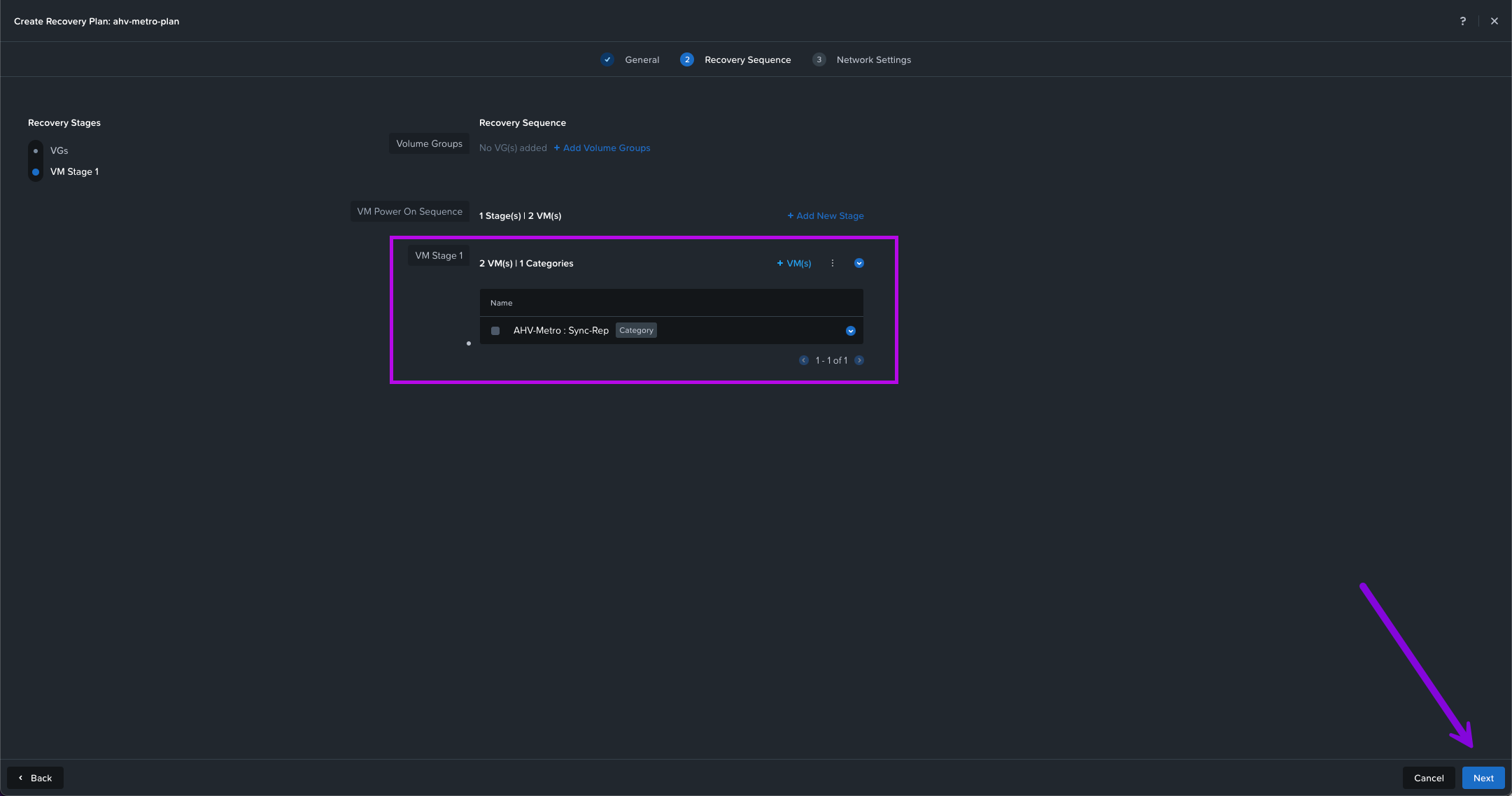
VM Stage 1? So should I create a VM Stage 2? Why would I need other Stages?
5. Next we'll need to configure the Network Settings. Since one of the steps I've listed out during the prerequisites was to make sure the networks exist in both the Primary and Recovery locations. We'll select Stretch Network for this configuration.
Your situation will vary as selecting Non-Stretch networks will have different networks on both sites. This will usually involve some re-IPing on the recovery location. Or even the same networks on both sides (ie. same VLAN IDs and IP ranges) which still falls under Non-Stretch networks since both sites are on different broadcast domains.
Once you determine which Network Type you have, select the drop downs and choose the network for both Primary and Recovery. Make sure to add the Gateway IP / Prefix Length. Once done, click on Create in the bottom right.
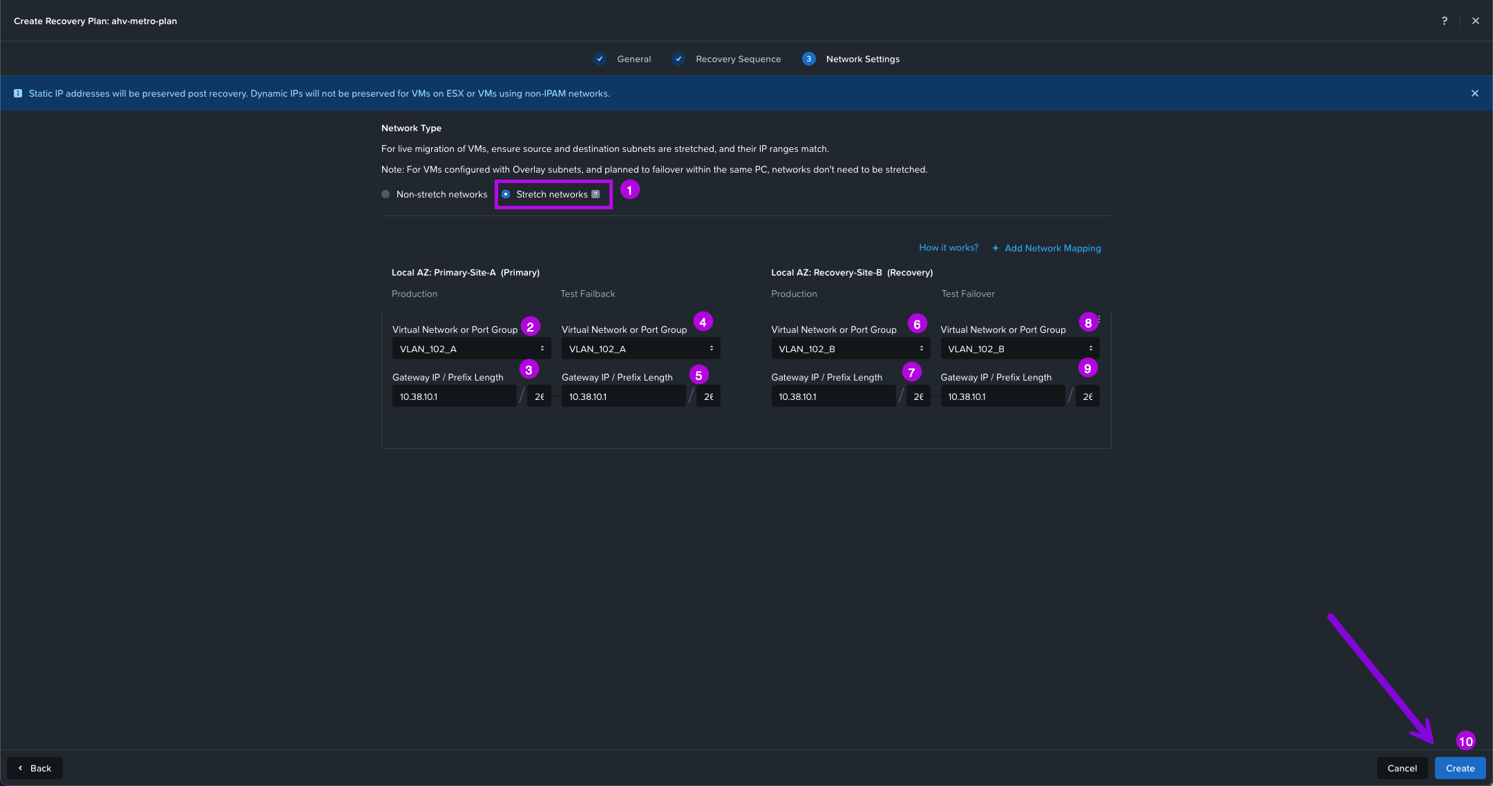
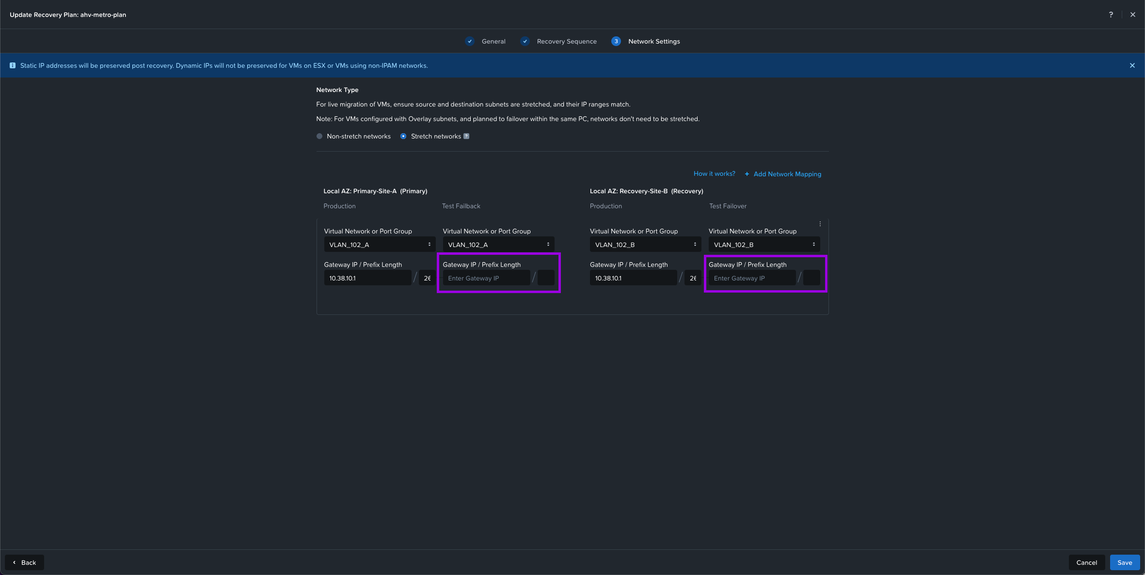
Optional: You can also leave out the gateway under Test Failback and Test Failover if you'd like to perform a Test on your recovery plan and don't want the networks to be routed on the VMs that get duplicated to test. For more details on this click here.
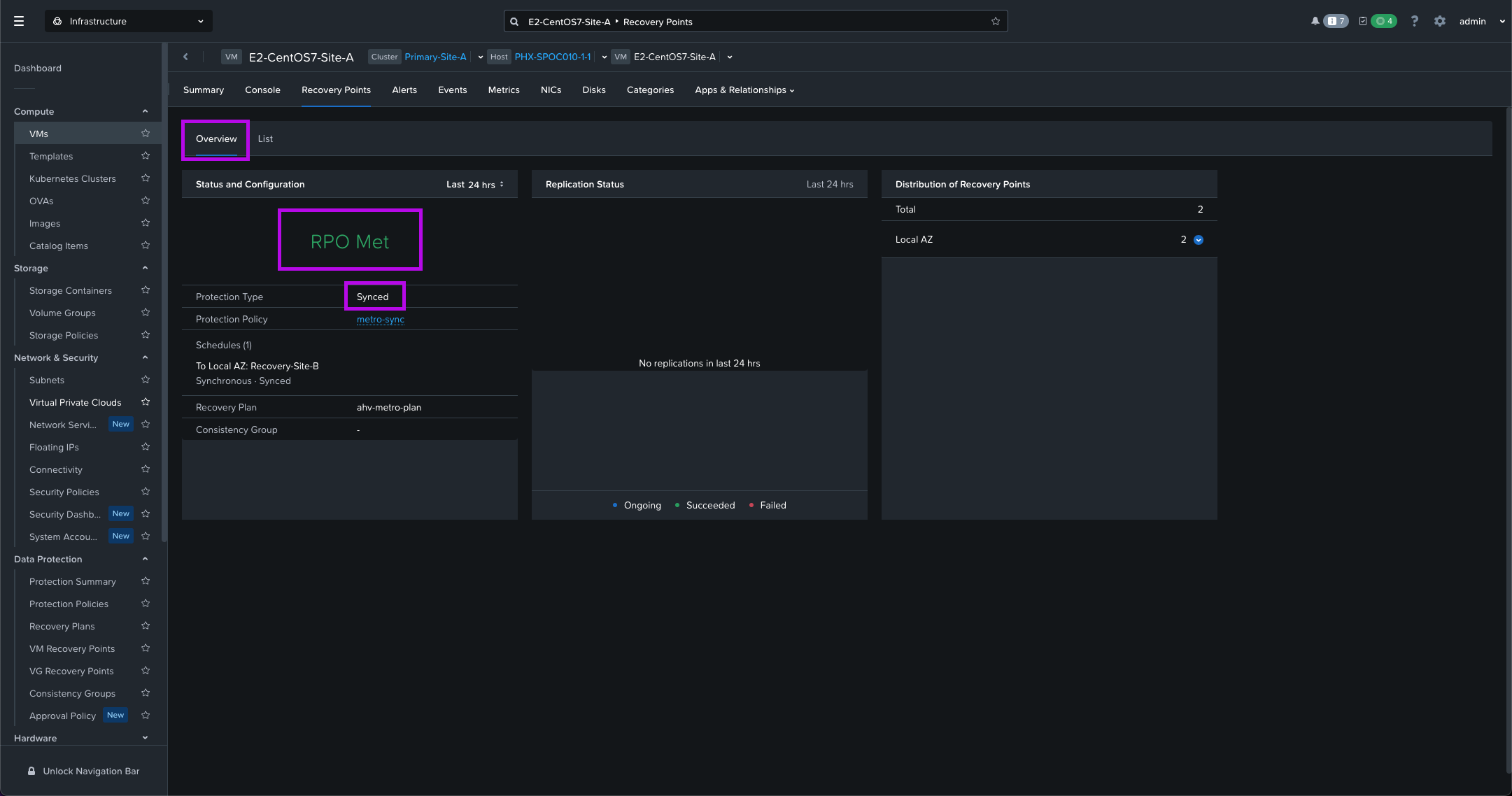
6. Monitor your tasks to completion and once done, we'll now have a newly minted Recovery Plan. You can also navigate to Compute > VMs and click on one of the VMs we added to our Category. From here navigate over to Recover Points > Overview to see that the RPO for synchronous replication is met.
Testing AHV Metro Availability Failover
Finally, AHV Metro is all setup and configured. We can run a few tests to make sure everything was setup correctly. One of the first tests we can run is a Live Migration Across Clusters. We'll be able to test our network connectivity once the VMs have Live Migrated to the Recovery cluster.
1. Live Migrate Across Clusters
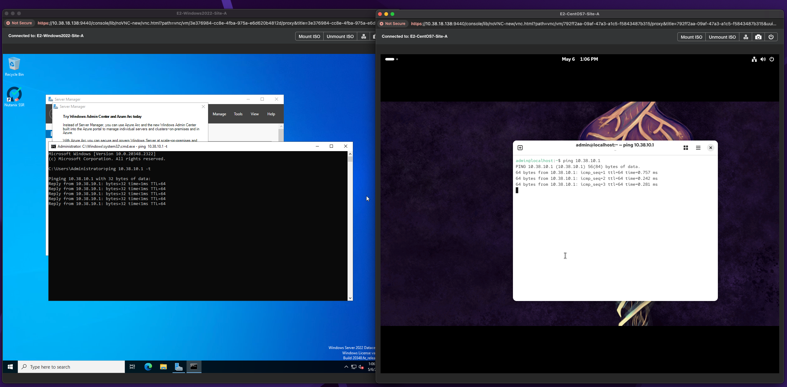
1. One of the first things to do before we Live Migrate is to launch the console for a VM by simply right clicking a VM and selecting Launch Console. Once you have logged into your VM, bring up a terminal session and simply put a constant ping on your gateway. In this instance my gateway is 10.38.10.1.
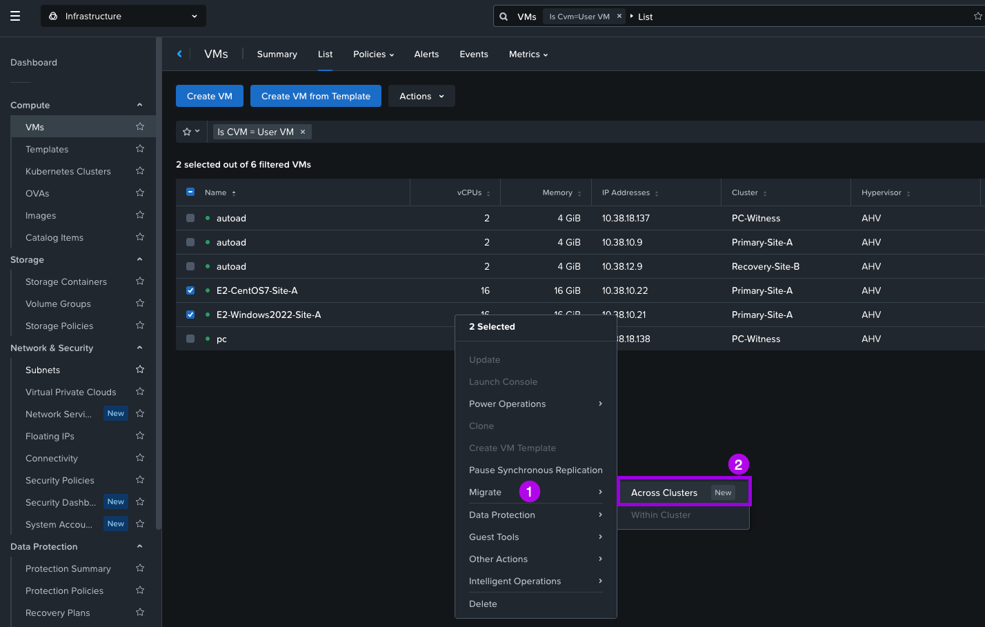
2. Navigate to the Compute > VMs and select the VMs you want to Live Migrate. Right click on the VMs once selected and navigate the menu to select Migrate > Across Clusters.
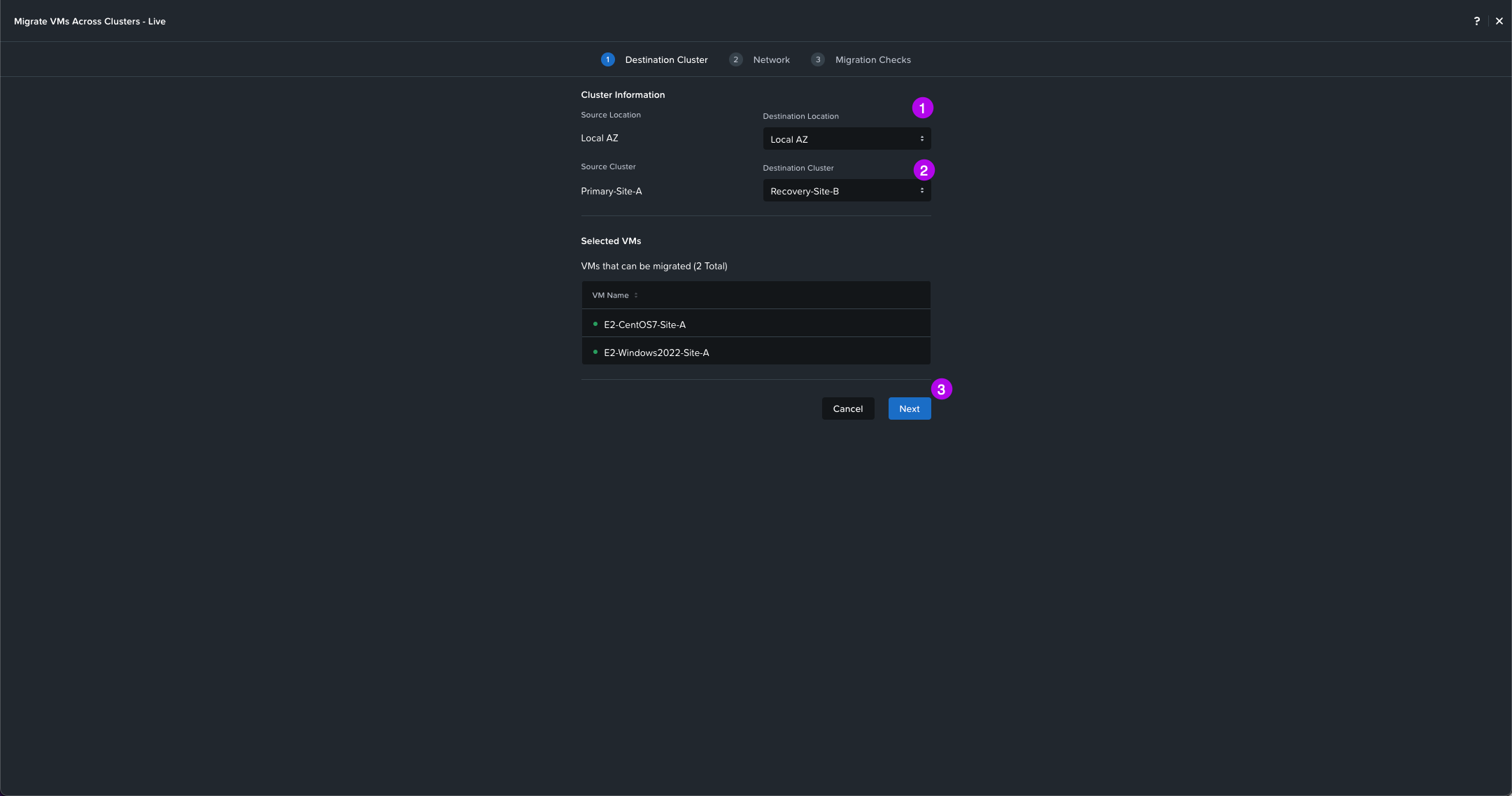
3. On this next screen you can see the VMs that will be migrating. Select your Destination Location AZ, then Destination Cluster which should be your recovery cluster. When done click on Next.
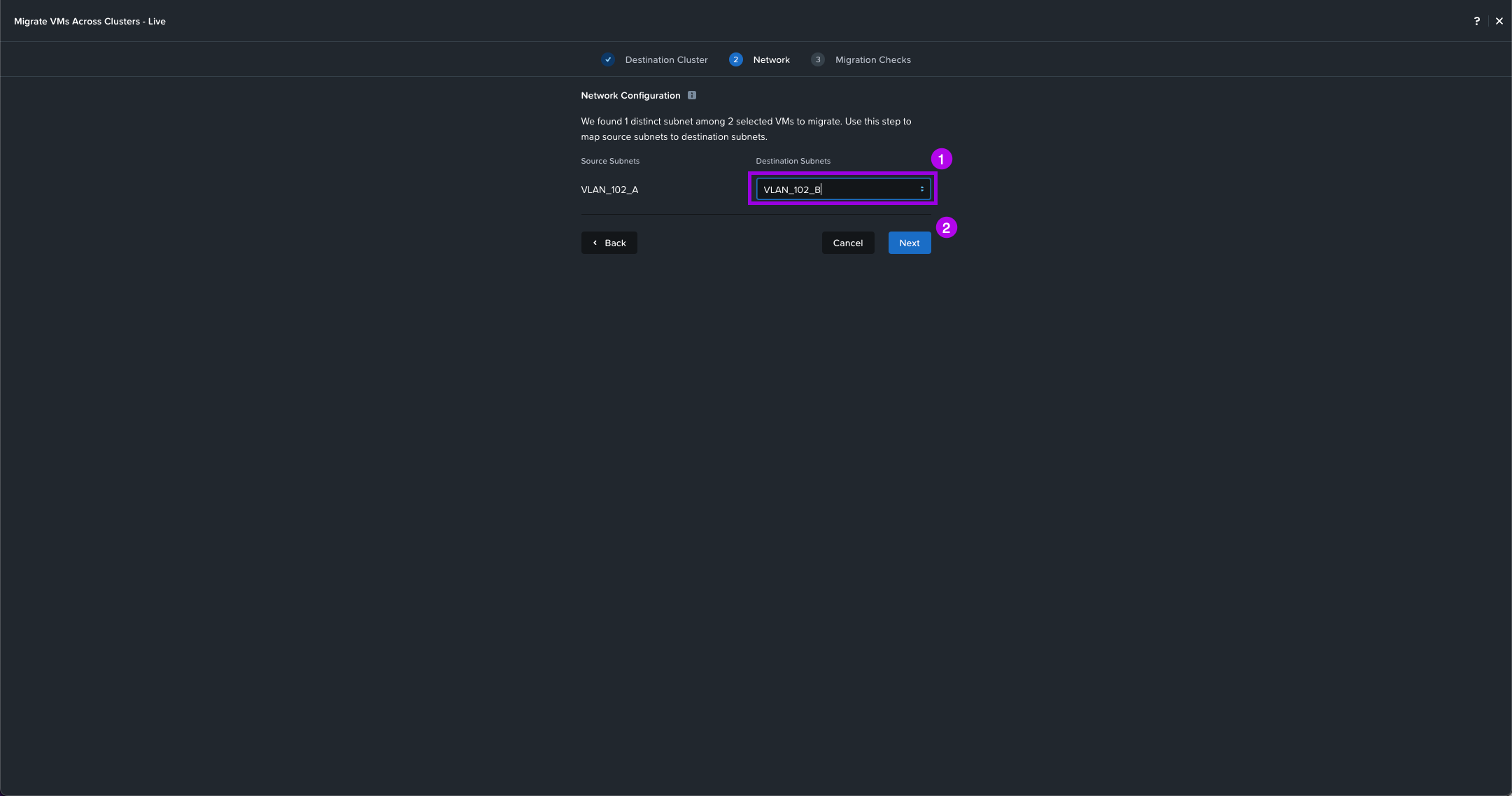
4. Select your Destination Subnet which should be the same L2 network that exists on the recovery cluster. Once selected click on Next.
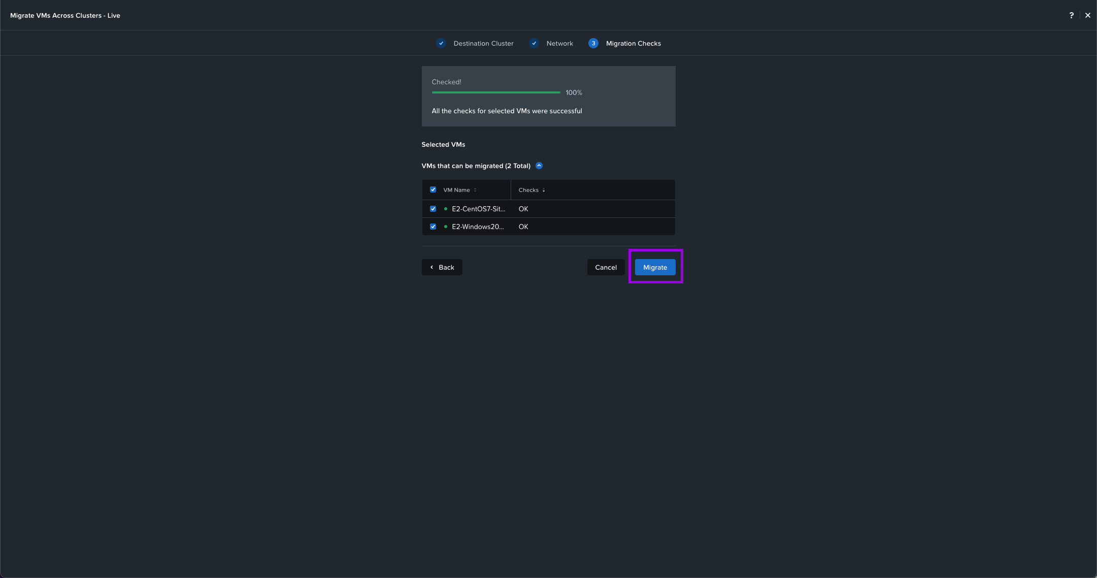
5. Some Migration checks will be performed such as cluster compatibility and network latency. Once all the checks are complete with no errors, click on Migrate.
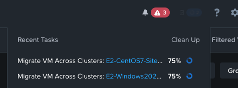
Simply monitor the recent tasks till completion.
Once complete, you'll notice that the VMs now reside in Recovery-Site-B. From here you'll need to launch another console session for the VMs since the previous session was launched from the Primary cluster. We can see that the VMs can still ping the gateway with no disconnect in network connectivity.
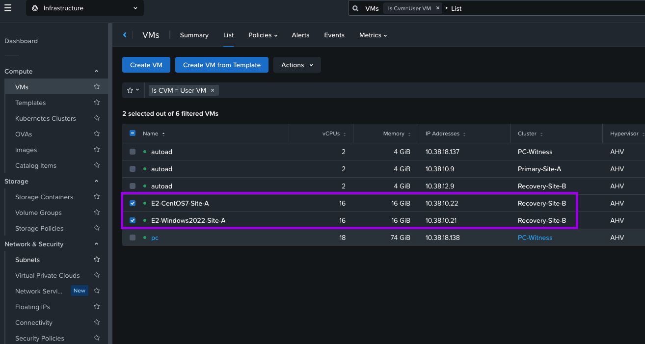
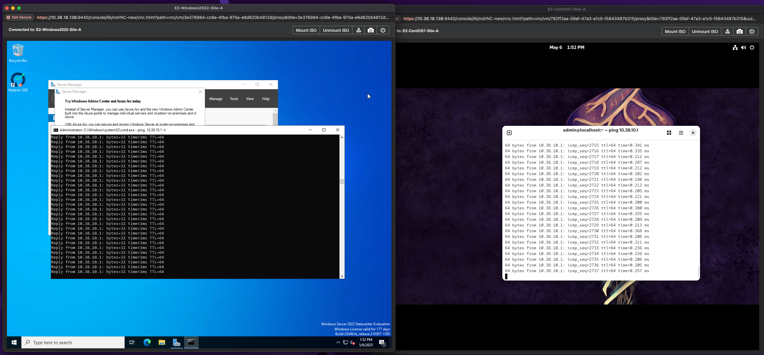
So at least now we know our network will work when the VMs failover. 😎 Now you can perform the Live Migration Across Cluster the other way to move the VMs back to the Primary site.
2. Validate & Perform Planned Failover
Since our Live Migration test to the Recovery site was successful, we can go-on and perform a failover following the steps below:
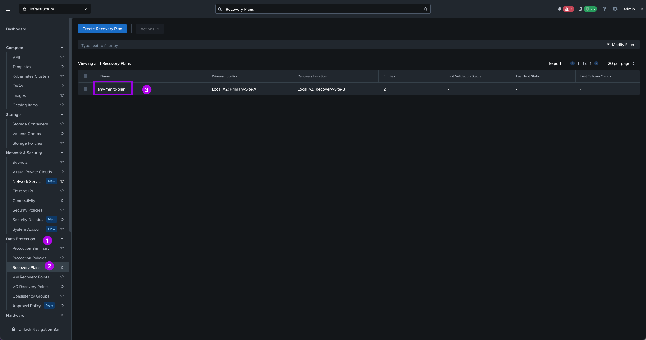
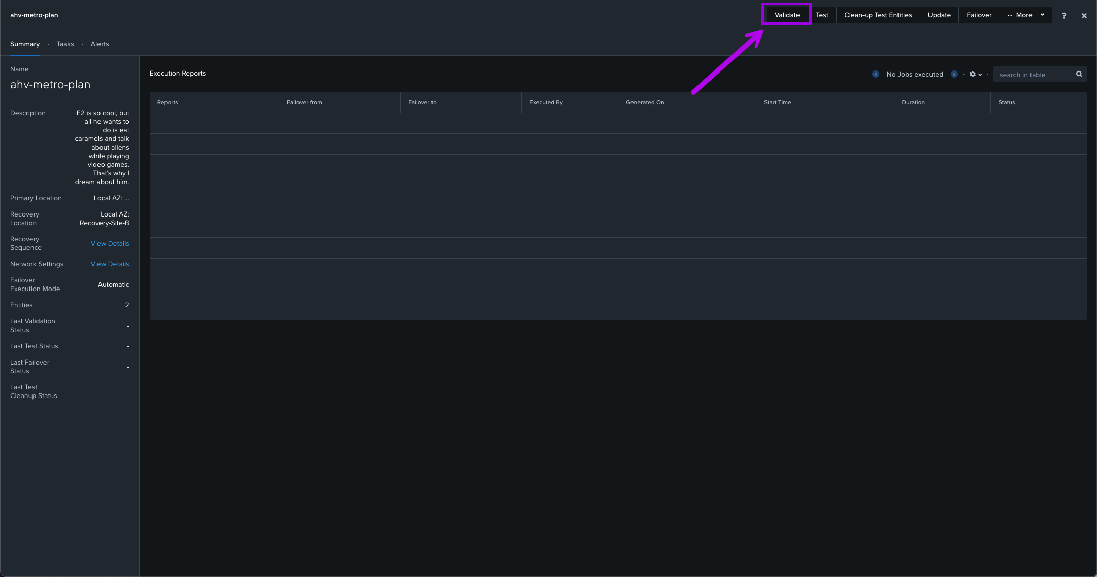
1. Navigate on the left menu down to Data Protection > Recovery Plans. Once here click on the Recovery Plan name that we created in a step above. From there we can click on Validate to make sure there are no warnings and errors and that our Recovery Plan is solid.
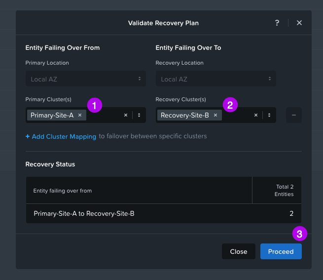
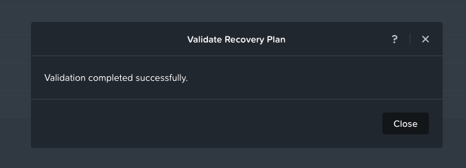
2. Another window will pop-up and just make sure to fill out your Primary Cluster and Recovery Cluster. Once done, click on Proceed. After it checks for a bit you should see the output of your Validation. The desired result is that Validation completed successfully.
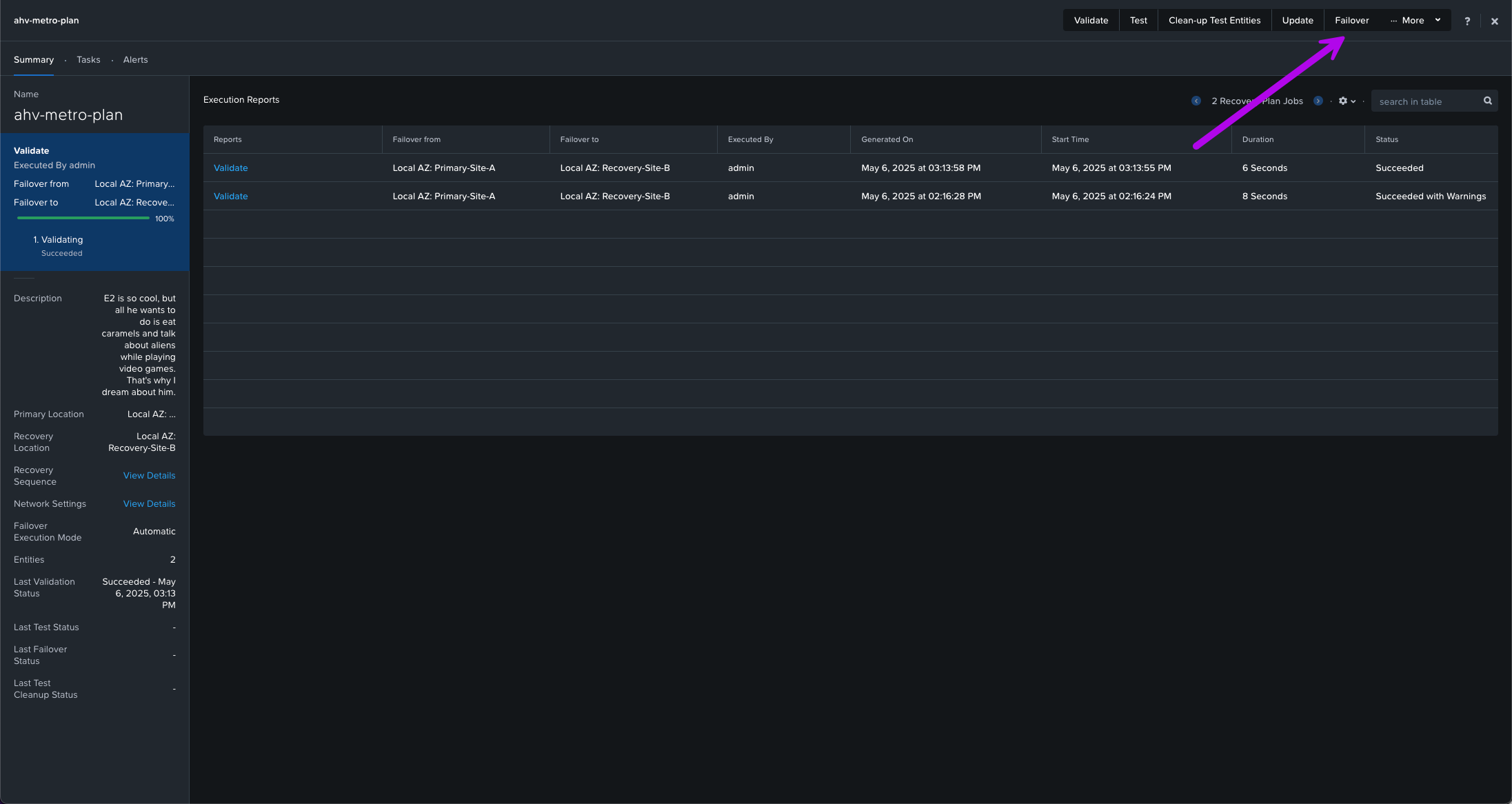
3. Now we can continue with the actual Failover. Back on the Recovery Plan we created, click on Failover at the top.
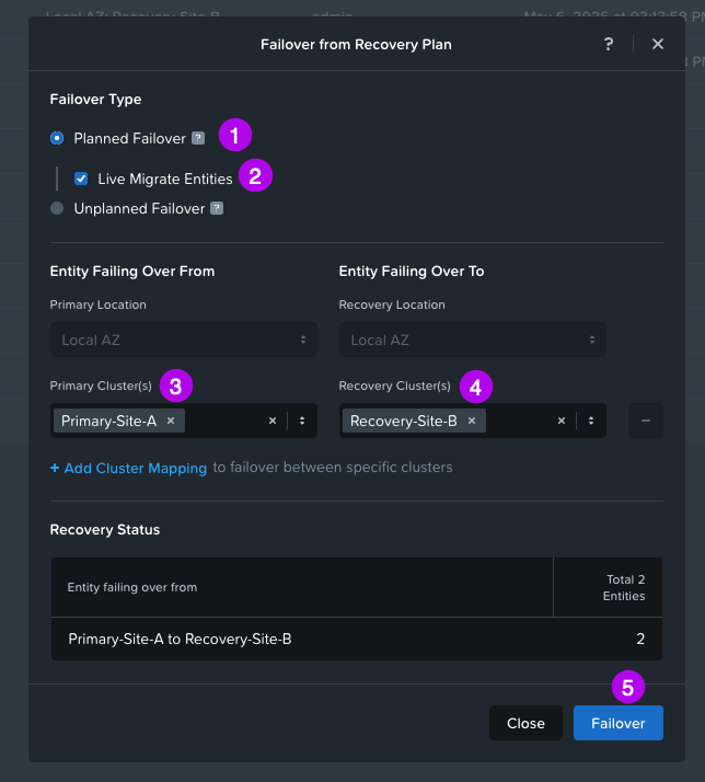
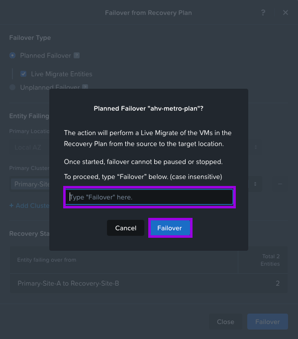
4. Next make sure Planned Failover is selected and click on Live Migrate Entities. Choose next your Primary Cluster and your Recovery Cluster. Then finally click on Failover. Another box will pop-up to make sure you reeeeally want to perform this failover. Type the word "Failover" and click on the Failover button.
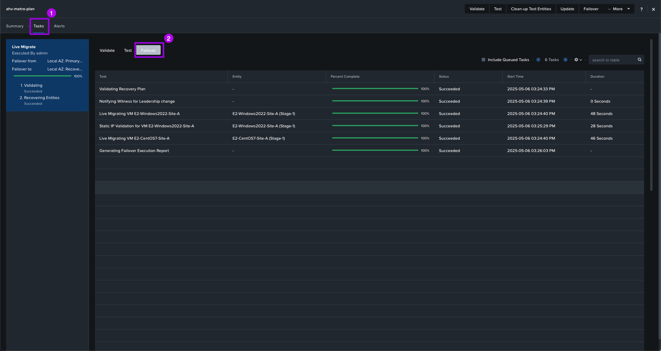
5. Monitor the Failover status buy clicking on Tasks > Failover.
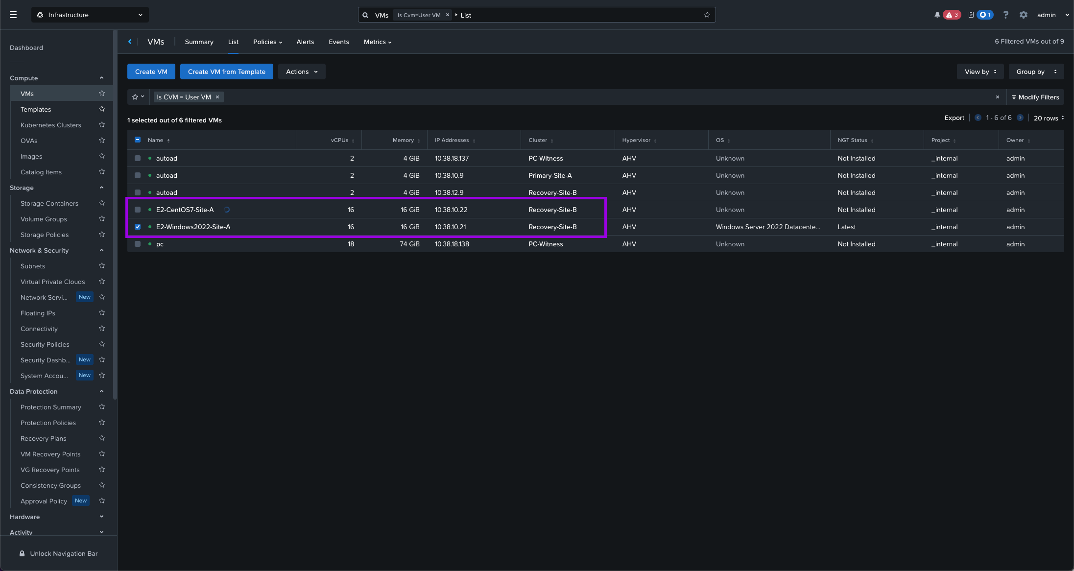
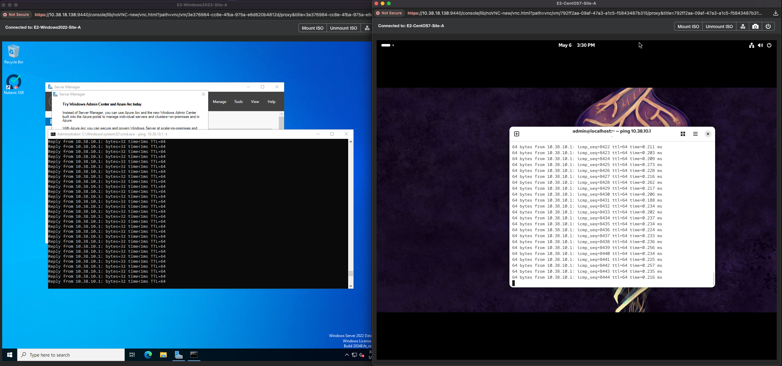
Once complete, navigate over to your Compute > VMs view. Make sure the VMs are now on the Recovery-Site-B. Then launch a console window and validate that the VMs are still communicating on the network and can ping the gateway.
6. Finally you can perform a Live Migration of the VMs back to the Primary site.
What reasons would I have into doing a "Planned Failover?"
2a. Optional - Built-in Isolated Failover Testing
Built within the Recovery Plan is the ability to perform an isolated test failover of your protected VMs. So once you have your recovery plan set with the workloads you want to protect, this Test option will allow test VMs to be duplicated into their own isolated network that you define. This is useful because it will allow you to test full applications that are isolated to ensure the applications still work after failing over to the Recovery cluster.
Also, you can keep the VMs on the same network but simply remove the gateway so that they aren't routable outside of their network. This is how I have it configured for this example.
**Note: Make sure to remove the gateway if using the same network as this can cause issues such as IP conflicts, corrupted data, etc.**

In order to perform this follow the steps below:
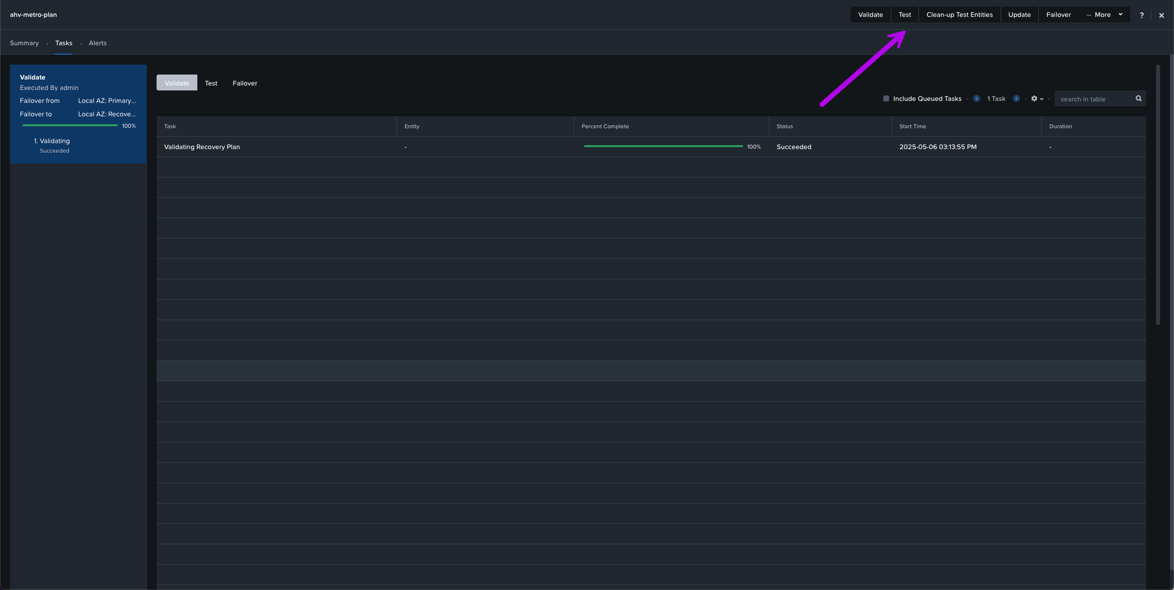
1. In your Recovery Plan, click on the Test option located at the top of the screen.
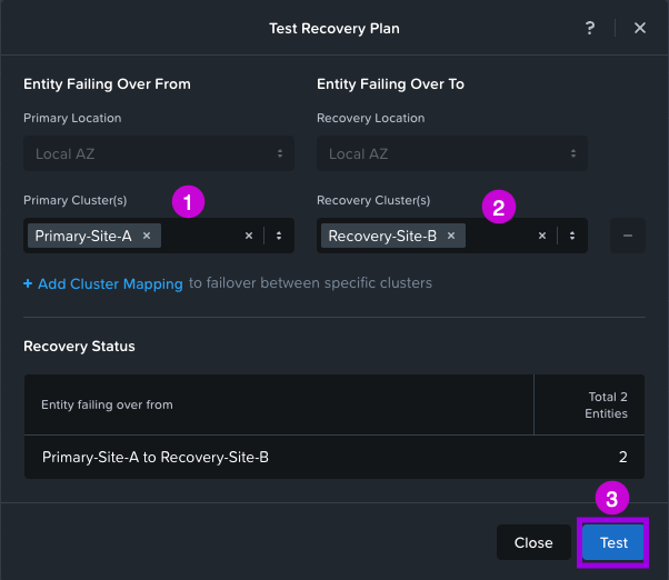
2. A small window will pop-up. From here fill in both your Primary Cluster and Recovery Cluster. Then click on Test.
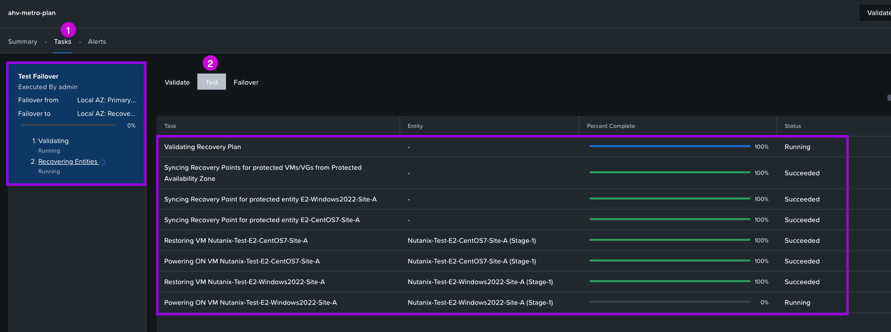
3. Once done, you'll be able to monitor the tasks by navigating over to Tasks > Test. From here you'll be able to view the status of the testing creation.
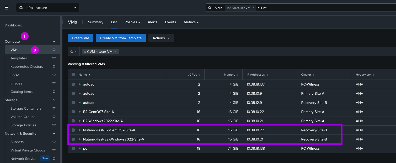
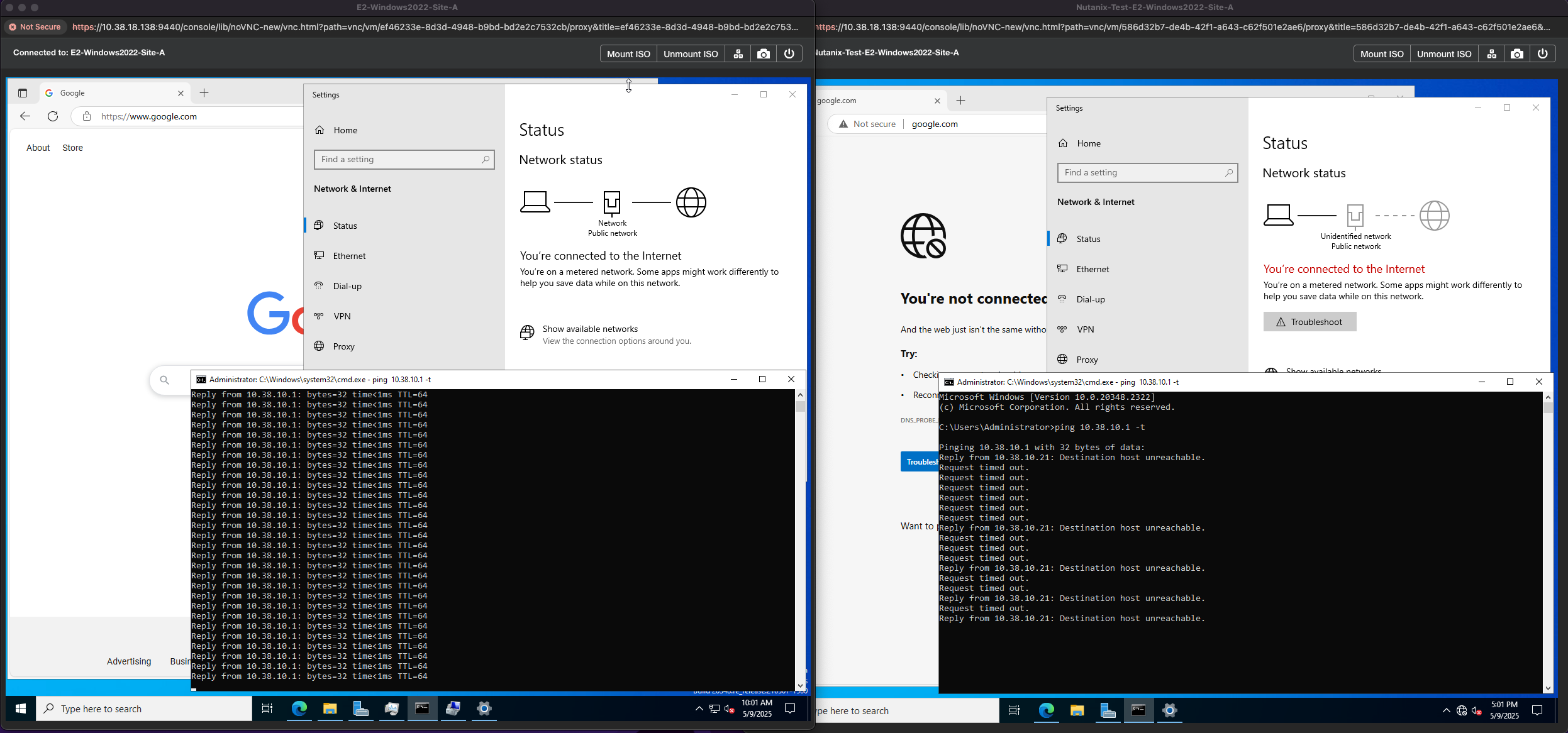
4. After completion, navigate over to Compute > VMs. You'll now notice some duplicate VMs with the prefix Nutanix-Test which were created by this test process. If you login to the VMs and try to ping the gateway, access the internet or check the network adapter settings none of those will work or display connectivity.
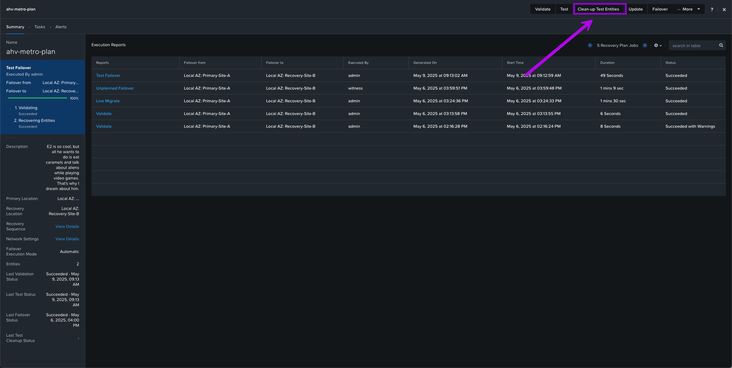
5. Once you are complete and satisfied with your testing, simply navigate back over to Data Protection > Recovery Plans then click into your recovery plan. From here click on the option next to Test called Clean-up Test Entities. When the small window pops up, click on Clean Up.
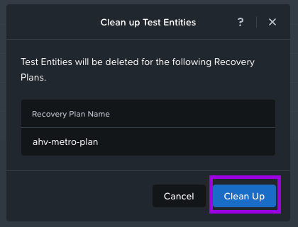
This will initiate the Clean Up process to delete those test VMs.

3. Unplanned Failover / Disaster
For the final test, we'll perform an "unplanned failover" / disaster scenario. I'll do so by remotely logging into the actual physical host via IPMI and sending a command to Power Off. This way it would simulate a real life unplanned outage.
1. Navigate to your dashboard and locate the Cluster Quick Access tile. Click on your Primary Cluster which will open in a new tab.
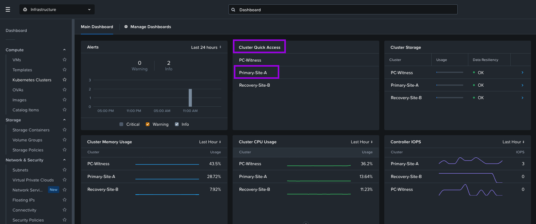
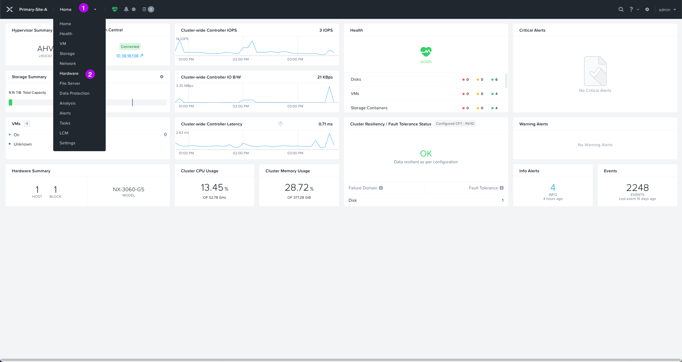
2. From here, we'll want to navigate down to the Hardware option in the drop down menu.
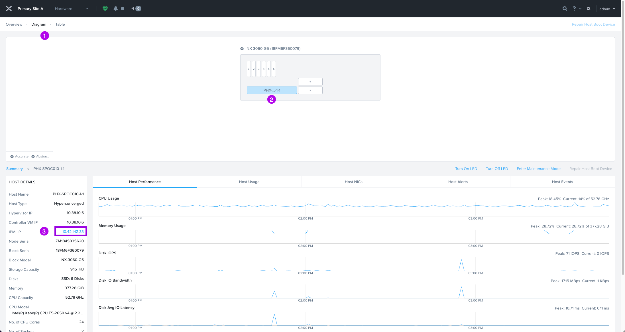
3. Once at the Hardware page, click on the Diagram tab at the top. Next click on the actual server node depicted in the image. On the bottom left hand side, you'll have the IPMI IP which is hyperlinked. Click on that to open a new tab into the physical server.
**NOTE: Your view may be different depending on the type of hardware you are running. This example is running on some older Nutanix-NX nodes.**
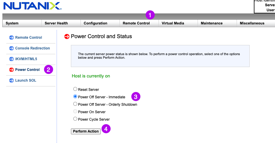
4. Login to the management interface of the server. Navigate to where you can remotely power off the server. In my case with a Nutanix-NX node, it'll be under Remote Control > Power Control. Then click the radio button for Power Off Server - Immediate and then finally click on Perform Action.
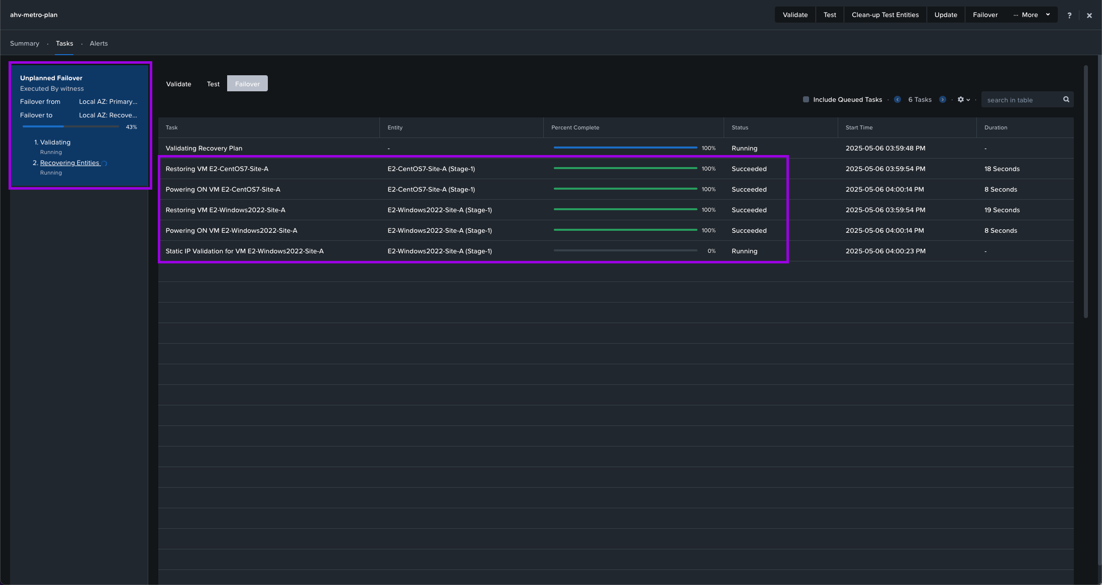
5. If you flip back over to your Recovery Plan page and navigate to Tasks > Failover. You'll be able to see that an unplanned failover occurred and the Recovery Plan we created has initiated.
Next navigate to your Compute > VMs view and you'll see the VMs have essentially performed an HA event. They'll get powered on in the Recovery site using real-time replicated data allowing for a fast recovery. As you can see in the screenshot those VMs are now operating on Recovery-Site-B. The original VMs are left there as an orphaned entry which will get cleaned up automagically after the Primary site is back up.
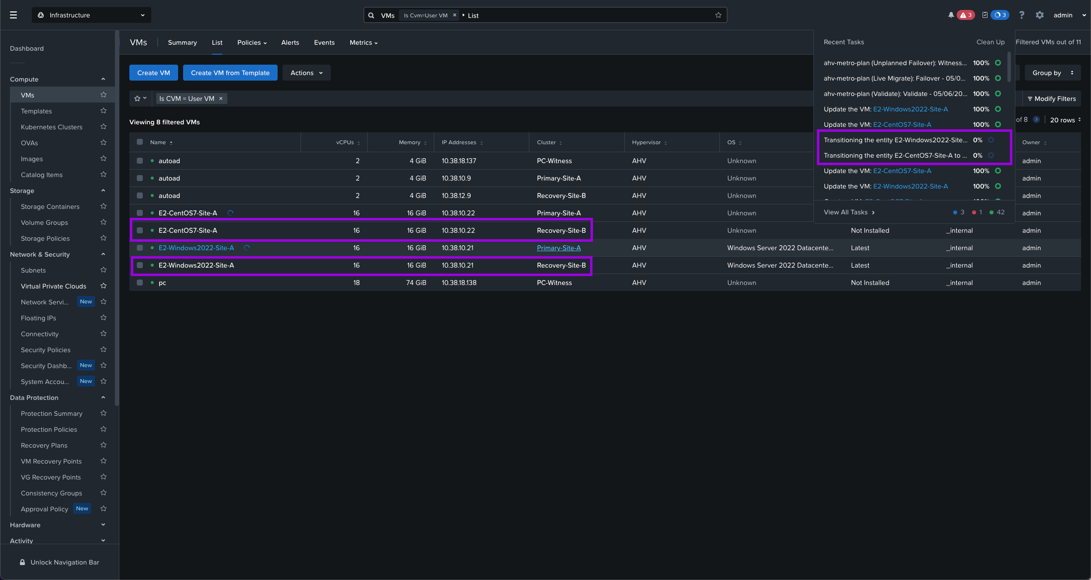
Finally if you launch a console on the VMs. You'll see that they went through a HA cycle which restarted them on the Recovery site. Note the uptime. Also, perform a ping on the gateway just to make sure everything is communicating correctly and in order.
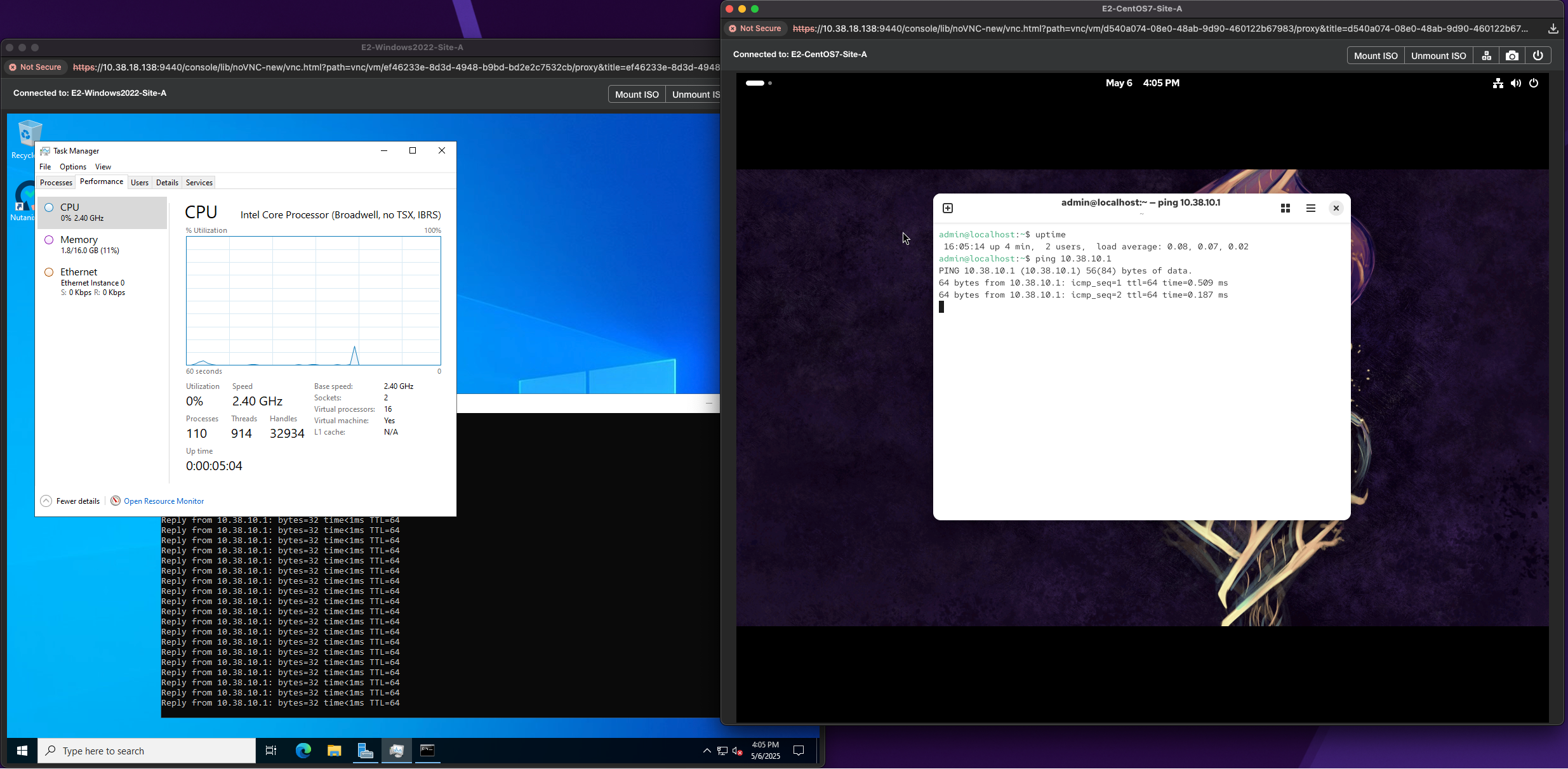
With that, all that's left to do is power on the server through the IPMI connection. Once powered on, manually migrate the VMs back to the Primary cluster. You can explore creating a reverse Recovery Plan which has your Primary and Recovery sites flipped and simply run a Failover on that plan which will cause all the VMs within that category to move back to the Primary site.
In other words, there are numerous ways to skin a cat. (Where did that expression even come from?)





Fantastic write up thanks for this ! straight to. the point and im gald you covered the network pre-work, very useful
Great read!